Table of Contents
Advertisement
ULN80 - 125, ULN80 - 165, ULN80 - 180, ULN80 - 199
ULN100 - 199, ULN100T - 199, ULN100 - 250, ULN100 - 270
WARNING: if the information in these instructions is not
followed exactly, a fire or explosion may result causing
property damage, personal injury or death.
Do not store or use gasoline or other flammable vapors
and liquids in the vicinity of this or any other appliance.
WHAT TO DO IF YOU SMELL GAS.
•
Do not try to light any appliance.
•
Do not touch any electrical switch, do not use any phone
in your building.
•
Immediately call your gas supplier from a neighbor's
phone. Follow the gas supplier's instructions.
•
If you cannot reach your gas supplier, call the
fire department.
Installation and service must be performed by a qualified
installer, service agency or the gas supplier.
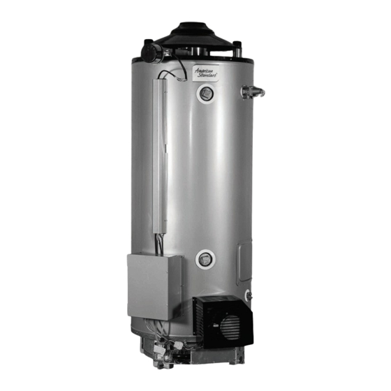
NEW STANDARDS IN WATER HEATING
ULN100 - 300, ULN80 - 399, ULN80 - 512
Operation, installation
Commercial Gas Water Heater
and service manual
Advertisement
Table of Contents


Need help?
Do you have a question about the ULN80-125 and is the answer not in the manual?
Questions and answers