
Related Manuals for Keysight N1930 B Series


Summary of Contents for Keysight N1930 B Series
- Page 1 N1930xB Physical Layer Test Systems N1930xB Physical Layer Test System Software which supports VNA-Based and TDR-Based Physical Layer Test System Hardware INSTALLATION GUIDE...
- Page 4 FAR 52.227-19 (June 1987) or any equivalent agency regulation or contract clause. Use, duplication or disclosure of Software is subject to Keysight Technologies’ standard commercial license terms, and non-DOD Departments and Agencies of the U.S.
- Page 5 Assistance Product maintenance agreements and other customer assistance agreements are available for Keysight Technologies products. For information about these agreements and for other assistance, contact Keysight. Refer to Contacting Keysight. Safety and Regulatory Information The safety and regulatory information pertaining to this product is located in...
- Page 6 Documentation Map The online Help files are in the PLTS software, offering quick reference to user documentation. Click Help on the menu bar. This Installation Guide helps you to with PLTS software and hardware installation. PLTS Documentation Online All PLTS documentation, including the very latest online version of the PLTS Help file, can be found at: Technical Support: N19301B PLTS Base Analysis.
-
Page 7: Table Of Contents
Contents Contents Installing the VNA-Based Physical Layer Test System Hardware ..................10 Step 1. Set Up the Personal Computer ................ 12 Step 2. Verify your System Shipment................13 Step 3. Set Up the Network Analyzer ................16 Step 4. Attach the Network Analyzer to the Test Set ........... 17 (N4420B or N4421A/B Test Set Only) .................. - Page 8 PLTS Installation Troubleshooting ................62 Connection Manager working with .NET and the T&M Toolkit ..........63 PLTS does not recognize the Keysight USB to GPIB adapter..........63 Other Keysight USB to GPIB Adapter Problems ..............64 Problems with the VISA Layer ....................65 Problems with VISA COM (SOAP Error) ..................
- Page 9 I/O Troubleshooting Steps ......................70 Missing Microsoft Component ....................74 PLTS Hardware Troubleshooting .................. 75 Troubleshooting PLTS Using a Tektronix CSA8000 or TDS8000 ..........76 Contacting Keysight...................... 82 Safety and Regulatory Information ........... 83 Safety Information ......................84 Safety Symbols......................... 84 Instrument Markings ........................
-
Page 10: Installing The Vna-Based Physical Layer Test System Hardware
Installing the VNA-Based Physical Layer Test System Hardware... - Page 11 Installing the VNA-Based Physical Layer Test System Hardware The Physical Layer Test System (PLTS) consists of the following items: • Personal computer (PC) • VNA-based system (Network analyzer and S-parameter test set) • PLTS software The installation procedure in this chapter will lead you through setting up the hardware (the PC and the VNA-based system).
-
Page 12: Step 1. Set Up The Personal Computer
4 GB 6 GB+ 6 GB+ Virtual Memory GPIB Interface Keysight 82357A USB/GPIB Interface for No GPIB connection is required to utilize Windows or supported GPIB card (any PLTS in the off-line mode. Saved (stored) National Instruments or Keysight 82340/41... -
Page 13: Step 2. Verify Your System Shipment
20 lb. (9 kg). 2. Carefully inspect the system hardware to make sure that it was not damaged during shipment. NOTE If your test system was damaged during shipment, contact Keysight Technologies. Refer to Contacting Keysight. - Page 14 Installing the VNA-Based Physical Layer Test System Hardware Step 2. Verify your System Shipment 4. Check the accessories that were shipped with your system. Your network analyzer accessories will be checked during the network analyzer setup. Item Nr Part Number Part Description 8120-3445 GPIB Cable (3 feet)
- Page 15 Installing the VNA-Based Physical Layer Test System Hardware Step 2. Verify your System Shipment 5. If you ordered any of the following options, check the parts. Option 1CP is shipped in a separate container. Option Number Item Part Description Number Rack mount flange kit (For use with handles) Handles (set of 2) Precision 50-ohm cables (4)
-
Page 16: Step 3. Set Up The Network Analyzer
Installing the VNA-Based Physical Layer Test System Hardware Step 3. Set Up the Network Analyzer Step 3. Set Up the Network Analyzer 1. Using the network analyzer’s Installation and Quick Start Guide, set up the network analyzer. 2. If you are installing your network analyzer in an equipment rack, be sure to leave at least 2 rack units of space below the analyzer to install the test set. -
Page 17: Step 4. Attach The Network Analyzer To The Test Set
Installing the VNA-Based Physical Layer Test System Hardware Step 4. Attach the Network Analyzer to the Test Set Step 4. Attach the Network Analyzer to the Test Set (N4420B or N4421A/B Test Set Only) If your test set is not an N4420B, an N4421A, or an N4421B, continue with Step 5. -
Page 18: Preparing The Test Set
Installing the VNA-Based Physical Layer Test System Hardware Step 4. Attach the Network Analyzer to the Test Set Preparing the Test Set 4. Remove the trim strip from the top of the front frame. 5. Install the four lock links to the top of the front frame using eight screws. Attaching the Network Analyzer to the Test Set 6. - Page 19 Installing the VNA-Based Physical Layer Test System Hardware Step 4. Attach the Network Analyzer to the Test Set 7. Secure the network analyzer’s lower locking feet to the test set’s upper locking feet by inserting the shorter two screws between the two pairs of locking feet, one on each side of the instrument as shown below.
-
Page 20: Step 5. Install The Test System On A Bench Top Or In An Equipment Rack
Installing the VNA-Based Physical Layer Test System Hardware Step 5. Install the Test System on a Bench Top or in an Equipment Rack Step 5. Install the Test System on a Bench Top or in an Equipment Rack The test system can be installed on a bench top or in an equipment rack. In all installations, consider the following ventilation requirements when deciding where to set up your test system. -
Page 21: To Install On A Bench Top
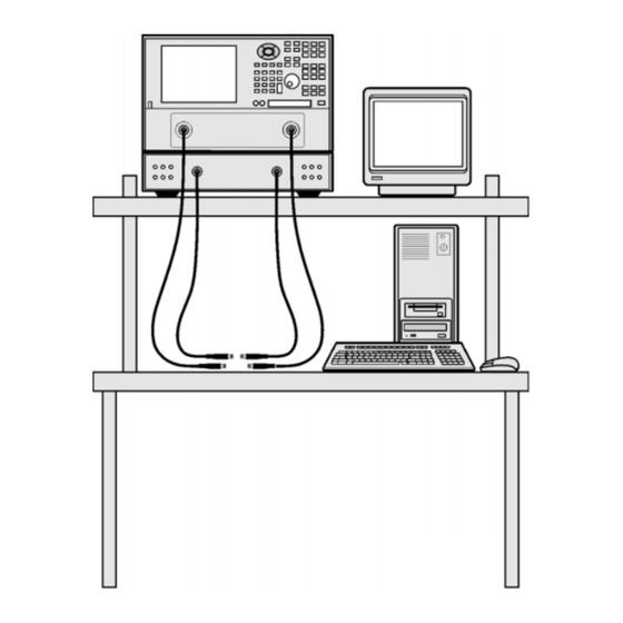
Installing the VNA-Based Physical Layer Test System Hardware Step 5. Install the Test System on a Bench Top or in an Equipment Rack To Install on a Bench Top 1. Place the test set and the network analyzer on a bench top. In the example illustration shown below, the system is placed on a riser as an alternative to the bench top. -
Page 22: To Install In An Equipment Rack
• Installation Instructions 2 Flanges • Installation Instructions NOTE If any items are damaged or missing from a kit, contact us (refer to Contacting Keysight) to order a replacement kit. Items within these kits are not individually available. Chapter 1... - Page 23 Installing the VNA-Based Physical Layer Test System Hardware Step 5. Install the Test System on a Bench Top or in an Equipment Rack 2. Install the rails into the equipment rack using the instructions provided. Consider that the test set is two rack units high (3.5 inches). Mount the test set immediately below the network analyzer.
- Page 24 Installing the VNA-Based Physical Layer Test System Hardware Step 5. Install the Test System on a Bench Top or in an Equipment Rack 4. Remove the feet before cabinet mounting the analyzer using the directions imprinted on the feet. 5. Ensure there is adequate clearance between the system cabinet and the sides and back of the test system for adequate ventilation.
- Page 25 Installing the VNA-Based Physical Layer Test System Hardware Step 5. Install the Test System on a Bench Top or in an Equipment Rack 6. Lift the test set and slide it onto the rails that you installed earlier from the front of the equipment rack.
-
Page 26: Step 6. Make The Interconnections Between The S-Parameter Test Set And The Network Analyzer
Installing the VNA-Based Physical Layer Test System Hardware Step 6. Make the Interconnections between the S-Parameter Test Set and the Network Analyzer Step 6. Make the Interconnections between the S-Parameter Test Set and the Network Analyzer 1. Locate your system or test set and network analyzer on the following pages for information describing the interconnections between the test set and the network analyzer. - Page 27 Installing the VNA-Based Physical Layer Test System Hardware Step 6. Make the Interconnections between the S-Parameter Test Set and the Network Analyzer Chapter 1...
- Page 28 Installing the VNA-Based Physical Layer Test System Hardware Step 6. Make the Interconnections between the S-Parameter Test Set and the Network Analyzer CAUTION When connecting the interconnect cables described in the remaining pages of this section, be careful to install the interconnect cables correctly. The longer end of the interconnect cable connects to the network analyzer front panel connector.
-
Page 29: N1957B Test System Interconnections
Installing the VNA-Based Physical Layer Test System Hardware Step 6. Make the Interconnections between the S-Parameter Test Set and the Network Analyzer N1957B Test System Interconnections (N4421B Test Set with E8364B/C) CAUTION Damage to the interconnect cable can result from improper orientation of the cable. Refer to page for detailed information regarding the correct cable orientation. - Page 30 Installing the VNA-Based Physical Layer Test System Hardware Step 6. Make the Interconnections between the S-Parameter Test Set and the Network Analyzer Call Out Cable Part From Sequence Number Network Analyzer Test Set Z5623-20215 REF 1 SOURCE OUT REF 1 R1 OUT Z5623-20215 REF 1 RCVR R1 IN REF 1 RCVR R1 IN...
-
Page 31: N1955B Test System Interconnections
Installing the VNA-Based Physical Layer Test System Hardware Step 6. Make the Interconnections between the S-Parameter Test Set and the Network Analyzer N1955B Test System Interconnections (or N4420B Test Set with E8363B/C Network Analyzer) CAUTION Damage to the interconnect cable can result from improper orientation of the cable. Refer to page for detailed information regarding the correct cable orientation. - Page 32 Installing the VNA-Based Physical Layer Test System Hardware Step 6. Make the Interconnections between the S-Parameter Test Set and the Network Analyzer Call Out Cable Part From Sequence Number Network Analyzer Test Set Z5623-20215 REF 1 SOURCE OUT REF 1 R1 OUT Z5623-20215 REF 1 RCVR R1 IN REF 1 RCVR R1 IN...
-
Page 33: N1935A And N1953B Test System Interconnections
Installing the VNA-Based Physical Layer Test System Hardware Step 6. Make the Interconnections between the S-Parameter Test Set and the Network Analyzer N1935A and N1953B Test System Interconnections (or N4419B Test Set with E8362B/C or N5230A/C Option 225 Network Analyzer) CAUTION Damage to the interconnect cable can result from improper orientation of the cable. - Page 34 Installing the VNA-Based Physical Layer Test System Hardware Step 6. Make the Interconnections between the S-Parameter Test Set and the Network Analyzer Call Out Cable Part From Sequence Number Network Analyzer Test Set AD00756-1 REF 1 SOURCE OUT REF 1 SOURCE OUT AD00756-1 REF 1 RCVR R1 IN REF 1 RCVR R1 IN...
-
Page 35: Step 7. Set Up Pc To Plts Communication
Installing the VNA-Based Physical Layer Test System Hardware Step 7. Set up PC to PLTS Communication Step 7. Set up PC to PLTS Communication Below are several different configurations depending on the following: • Whether the PNA has a 1.1 GHz CPU (2 GPIB ports) •... -
Page 36: 1.1 Ghz Cpu Without Opt 550/551 - Legacy Mode
Installing the VNA-Based Physical Layer Test System Hardware Step 7. Set up PC to PLTS Communication 1.1 GHz CPU WITHOUT Opt 550/551 - Legacy Mode 1. Using a GPIB cable, connect the PNA GPIB Talker/Listener port to the test set GPIB port. 2. -
Page 37: 500 Mhz Cpu With Opt 550/551
Installing the VNA-Based Physical Layer Test System Hardware Step 7. Set up PC to PLTS Communication 500 MHz CPU with Opt 550/551 1. Connect a 82357A/B to the PNA USB and to the test set GPIB port. 2. Using a GPIB cable, connect the PNA GPIB port to the PC for control of the system. Or a LAN cable (dashed line) can be used in this configuration to control the PLTS system in either SICL-LAN, COM, or DCOM. - Page 38 Installing the VNA-Based Physical Layer Test System Hardware Step 7. Set up PC to PLTS Communication 2. Using a second GPIB cable, connect the PNA Talker/Listener GPIB port to the PC for control of the system. Or a LAN cable (dashed line) can be used in this configuration to control the PLTS system in either SICL-LAN, COM, or DCOM.
-
Page 39: Step 8. Power Up The S-Parameter Test Set
Installing the VNA-Based Physical Layer Test System Hardware Step 8. Power up the S-Parameter Test Set Step 8. Power up the S-Parameter Test Set 1. Ensure the available ac power supply meets the Power Source Requirements and the operating environment meets the Operating Environment Requirements listed below. Power Source Requirements Input Voltage Range 100 - 120 Vac... - Page 40 Installing the VNA-Based Physical Layer Test System Hardware Step 8. Power up the S-Parameter Test Set NOTE Perform Step 6 ONLY when both of the following are true. Otherwise, skip to Step * When using the Reference channel paths through the test set. See page 1-17 for more information.
-
Page 41: Installing The Tdr-Based Physical Layer Test System Hardware
Installing the TDR-Based Physical Layer Test System Hardware... - Page 42 PLTS software • TDR-based PLTS hardware (one of the following systems) — Keysight 86100A/B/C Infiniium DCA Wide-Bandwidth Oscilloscope equipped with one or two 54754A Differential 18 GHz TDR/TDT Plug-in Modules using the following firmware revisions: Keysight 86100A/B: Firmware Revision 03.06 or greater Keysight 86100C: Firmware Revision 04.00 or greater...
- Page 43 Installing the TDR-Based Physical Layer Test System Hardware NOTE If you have the VNA-based Physical Layer Test System, refer to 1 Installing the VNA-Based Physical Layer Test System Hardware for instructions on setting up that system. The following is a list of the installation steps to set up your TDR system hardware: •...
-
Page 44: Step 1. Set Up The Personal Computer
4 GB 6 GB+ 6 GB+ Virtual Memory GPIB Interface Keysight 82357A USB/GPIB Interface for No GPIB connection is required to utilize Windows or supported GPIB card (any PLTS in the off-line mode. Saved (stored) National Instruments or Keysight measurement files can be recalled at any 82340/41 or 82350 GPIB card) time for analysis. -
Page 45: Step 2. Set Up The Tdr System
Step 1. Set Up the Personal Computer. CAUTION Both the Keysight and Tektronix TDR systems, although not required, may be connected to a computer network. Connecting to a computer network may present security risks to your TDR system. Chapter 2... - Page 46 Keysight 86100A/B/C Infiniium Digital Communications Analysis Wide-Bandwidth Oscilloscope with: — Firmware: 86100A/B revision 03.06 or later / 86100C: revision 04.00 or later — 1 or 2 Keysight 54754A 18 GHz Differential TDR/TDT Plug-In Modules installed • Tektronix CSA8000 Communications Signal Analyzer Oscilloscope with: —...
-
Page 47: Step 3. Set Up The General Purpose Interface Bus (Gpib)
Each test system device must have a unique GPIB address. Check the GPIB address of your Keysight TDR system by selecting Remote Interface from the Utilities menu on the TDR display. To check the GPIB address of your Tektronix TDR system, refer to the programming manual for information. -
Page 48: Step 4. Power Up The Tdr System
Installing the TDR-Based Physical Layer Test System Hardware Step 4. Power up the TDR System Step 4. Power up the TDR System If you have not previously powered on your TDR system, start with step 1. If you have already powered on your TDR system, just review steps 1, 2, and 3 before continuing with step 4. -
Page 49: Installing The Plts Software
Installing the PLTS Software... -
Page 50: Important Plts Installation Notes
Modify, Repair, or Remove the application. Please select Repair. • Microsoft .NET Framework • Keysight IO Libraries & VisaCom Troubleshooting if you encounter problems with PLTS Installation. Chapter 3... -
Page 51: Step 1. Install Or Upgrade Plts Software
Not all releases have an upgrade version. The major releases, which have the third party component upgrades, will not have an upgrade install version. 1. You can download the PLTS software from the Keysight Software Management System (KSM) at http://www.keysight.com/find/softwaremanager. For instructions on downloading the software, refer to your entitlement certificate that you received via email. - Page 52 Custom: Select to choose the program features you want installed. Click on an icon to the left of the feature name to change how the feature is installed. 6. At the Custom Setup dialog click Keysight IO Libraries Suite <current rev> and select: This feature will not be available 7.
-
Page 53: Step 2. License The Physical Layer Test System Software
When requesting a license file, be sure to use a host ID of the machine where the license file will be installed. If it is a floating license, use the host ID of the floating license server (not the host ID of the machine where you will run the licensed Keysight software). Chapter 3... - Page 54 Installing the PLTS Software Step 2. License the Physical Layer Test System Software • When choosing among host IDs that are specific to the machine, ensure that you choose a permanent or stable host ID to identify your machine. For example: o In some cases (for example, on Linux machines), there may be host IDs that correspond to running virtual machines (VMs).
-
Page 55: Get Your License
2. Find the host ID of the machine to license — see Get Your Host ID above. 3. Visit www.keysight.com/find/softwaremanager and follow the steps to request a license. If you don’t have a myKeysight account, you will be guided to create one. -
Page 56: Specify A Remote License Server
Installing the PLTS Software Step 2. License the Physical Layer Test System Software 4. Click Browse, browse to the license file on your machine, and click Open. License files have the extension .lic. A typical license file Name looks like this: 10e7c6207e9c_1083337.lic. - Page 57 Step 2. License the Physical Layer Test System Software 2. Click on the Specify a Remote License Server button. The drop-down Choose Products list shows all licensed Keysight products installed on your machine. Select (check) the products that need to use the new license server(s). For each product, if license servers are already configured, they are listed underneath the product in the drop-down list.
- Page 58 Installing the PLTS Software Step 2. License the Physical Layer Test System Software 4. Type the port_number@host_Name of each server. If you have more than one server: • If you are specifying three servers in a three-server redundant configuration, separate them with commas. •...
-
Page 59: Step 3. Start The Physical Layer Test System Software
Step 3. Start the Physical Layer Test System Software Important Note: Before the first start of the PLTS software, the KAL license must be installed using the “Keysight PathWave License Manager” described in Step 2. License the Physical Layer Test System Software. -
Page 60: Troubleshooting
Troubleshooting... -
Page 61: Electrostatic Discharge
Figure 4-1 Static-Safe Workstation • static-control table mat and earth ground wire: part number 9300-0797 • wrist-strap cord: part number 9300-0980 • wrist-strap: part number 9300-1367 • heel-straps: part number 9300-1308 • floor mat: not available through Keysight Technologies Chapter 4... -
Page 62: Plts Installation Troubleshooting
This section provides some background and gives solutions for correcting PLTS installation problems. The following issues are covered in this section: • Connection Manager working with .NET and the T&M Toolkit • PLTS does not recognize the Keysight USB to GPIB adapter. • Problems with the VISA Layer •... -
Page 63: Connection Manager Working With .Net And The T&M Toolkit
Connection Manager working with .NET and the T&M Toolkit PLTS Connection Manager communicates with instruments and scans for instruments connected to the bus. The PLTS Connection Manager is built on Keysight's Test and Measurement Programmers Tool Kit (T&M Toolkit), which requires Microsoft's .NET package. Figure 4-2 shows PLTS and its dependencies on other software products and how it communicates with instruments. -
Page 64: Other Keysight Usb To Gpib Adapter Problems
To get the adapter to work for either case, make sure the PC is fully powered up and Windows is functional, then unplug the USB connection and reconnect the adapter. The Microsoft Operating System will find the new hardware and the details will be displayed in the Keysight Connection Expert dialog box similar to Figure 4-3. -
Page 65: Problems With The Visa Layer
When loading the Keysight I/O libraries second (as with PLTS), the Keysight VISA should be set as the primary VISA. Problems may occur leaving the Keysight VISA as secondary VISA. Refer to Figure 4-4 through Figure 4-8 for more details. To quickly check the... - Page 66 The VISA COM must be loaded for PLTS Connection Manager to work. If the IO libraries are already installed, uninstall then re-install the IO libraries. This can be done by re-installing PLTS or by down loading the IO libraries from the Keysight IO Libraries Suite web page: http://www.keysight.com/find/iolib Choose the Typical selection during the PLTS installation.
- Page 67 PLTS Installation Troubleshooting Figure 4-6 User Analytics Options Click Install. The Typical selection automatically loads the Keysight VISA COM and sets it as the primary VISA. See Figure 4-7. Figure 4-7 Keysight IO Libraries Suite 2019 Start Copying Files Screen If you chose the Custom selection, you must now choose how to install the VISA.
- Page 68 Troubleshooting PLTS Installation Troubleshooting Figure 4-8 Keysight IO Libraries Custom Installation Screen Chapter 4...
-
Page 69: Problems With Using National Instruments I/O Devices
5. Uninstall Keysight VISA Com using Start, Settings, Control Panel (Apps for Windows 10), and Add/Remove Programs (Uninstall for Windows 10). 6. Uninstall the Keysight T&M Toolkit using Start, Settings, Control Panel (Apps for Windows 10), and Add/Remove Programs (Uninstall for Windows 10). -
Page 70: I/O Troubleshooting Steps
8. Install the new NI driver. Reboot your computer if prompted. 9. Install NI VISA. Reboot your computer if prompted. 10. Install PLTS. Ensure that the Keysight VISA Layer is the primary VISA. See Figure 4-17. 11. For NI Labview code to run properly, you will need to enable TULIP Passport in NI Labview. - Page 71 Troubleshooting PLTS Installation Troubleshooting Use the Self-Test function in the Measurement & Automation Explorer to help troubleshoot any problems you encounter while using your GPIB hardware and the NI-488.2 software. Self- Test verifies that your GPIB hardware and the NI-488.2 software are installed correctly and able to perform basic I/O functions.
- Page 72 PLTS Installation Troubleshooting Troubleshooting the Keysight I/O Libraries Troubleshoot the Keysight I/O libraries by doing the following: 1. When the Keysight IO Control is running, an IO icon is displayed in the task bar as shown in Figure 4-12. Figure 4-12 Keysight IO Control Icon If the Keysight IO Control is not already running, click Start, Keysight Connection Expert.
- Page 73 Troubleshooting PLTS Installation Troubleshooting 3. To configure an interface, right-click the name of the interface and choose Edit. Figure 4-14 Edit settings for an 82357 USB/GPIB interface Dialog Box 4. For all GPIB interfaces used with PLTS, the VISA Interface Name and SICL Interface Name MUST BE THE SAME (including the case).
-
Page 74: Missing Microsoft Component
Troubleshooting PLTS Installation Troubleshooting Figure 4-15 Interactive IO Missing Microsoft Component When installing PLTS, if the following error is displayed, comctl32.ocx has to be installed and registered. 'Component 'comctl32' or one of its dependencies not correctly registered: a file is missing or invalid' Chapter 4... -
Page 75: Plts Hardware Troubleshooting
Line fuse not installed, or Install the line fuse. the first time you use it. incorrect line fuse installed. Excessive ripple in data. Load termination damaged by Contact Keysight Technologies. Contacting Keysight excessive RF power. for more information. Loose connections between VNA Check and torque the connectors. -
Page 76: Troubleshooting Plts Using A Tektronix Csa8000 Or Tds8000
Troubleshooting PLTS Hardware Troubleshooting Troubleshooting PLTS Using a Tektronix CSA8000 or TDS8000 PLTS is designed to use the following Tektronix equipment. • Tektronix CSA8000 Communications Signal Analyzer equipped with one or two 80E04 Dual Channel, 20 GHz TDR Sampling Modules using Firmware Revision 1.3.3 or greater •... - Page 77 Troubleshooting PLTS Hardware Troubleshooting • Set the Units to volts (V) c. In the Preset area: • Click the C1 button 4. On the TDR sampling module, verify that the red TDR LED and the yellow SELECT ON/OFF LED for channel 1 (CH 1) is lit. 5.
- Page 78 Make sure that GPIB Talk/Listen is selected in the GPIB Mode area. 2. Click the Start button in the lower left corner of the PC. Then select Programs, Keysight IO Libraries, then VISA Assistant to open the Visa Assistant dialog box.
- Page 79 Troubleshooting PLTS Hardware Troubleshooting Figure 4-17 Tektronix CSA8000 Response to *IDN? Button b. Select IEEE 488.2 in the Inst. Lang. area. c. Click the *IDN? button. The PC queries the instrument at the address requesting instrument information. The Tektronix instrument should reply with a response that lists the manufacturer, the model number, and some additional information that includes the firmware version (FV).
- Page 80 If it is found, continue with Verify the Tektronix Instrument Makes a PLTS Measurement. If it is not found, contact Keysight for assistance. Verify the Tektronix Instrument Makes a PLTS Measurement After PLTS has found and identified the Tektronix instrument, make a basic measurement using the following instructions.
- Page 81 4-19. Each measurement plot has been autoscaled. Figure 4-19 PLTS-Tektronix Measurement Example Plots 5. If your measurement results are similar to the measurement results shown above, your Tektronix instrument operates with the PLTS software. If it is not found, contact Keysight for assistance. Chapter 4...
-
Page 82: Contacting Keysight
Assistance with test and measurements needs and information on finding a local Keysight office are available on the Web at: http://www.keysight.com/find/assist If you do not have access to the Internet, please contact your Keysight field engineer. Make sure have the following information readily available: •... -
Page 83: Safety And Regulatory Information
Safety and Regulatory Information... -
Page 84: Safety Information
Safety and Regulatory Information Safety Information Safety Information Review to the safety information in this section before operating your physical layer test system. Safety Symbols The following safety symbols are used throughout this manual. Familiarize yourself with each of the symbols and its meaning before operating the physical layer test system. CAUTION Caution denotes a hazard. -
Page 85: Instrument Markings
Safety and Regulatory Information Safety Information Instrument Markings The instruction documentation symbol. The product is marked with this symbol when it is necessary for the user to refer to the instructions in the documentation. The AC symbol indicates the required nature of the line module input power. This symbol indicates separate collection for electrical and electronic equipment, mandated under EU law as of August 13, 2005. - Page 86 Safety and Regulatory Information Safety Information This symbol on all primary or secondary packaging indicates compliance to China standard GB 18455-2001. South Korean Certification (KC) mark; includes the marking's identifier code which follows the format: MSIP-REM-YYY-ZZZZZZZZZZZZZZ or KCC-REM-YYY-ZZZZZZZZZZZZ. Chapter 5...
-
Page 87: Safety Considerations
Safety and Regulatory Information Safety Information Safety Considerations Familiarize yourself with each of the safety considerations before operating the physical layer test system. NOTE Positioning the Test System for Use When setting up the physical layer test system for use, position the equipment so that the front panel power switch is easy to reach. - Page 88 Safety and Regulatory Information Safety Information Before Applying Power CAUTION Install the instrument so that the ON/OFF switch is readily identifiable and is easily reached by the operator. The ON/OFF switch or the detachable power cord is the instrument disconnecting device. It disconnects the mains circuits from the mains supply before other parts of the instrument.
- Page 89 Safety Information General WARNING To prevent electrical shock, disconnect the Keysight Technologies (N4415A, N4416A, N4417A, N4418A, N4419A/B, N4420B, and N4421A/B) S-parameter test set from mains before cleaning. Use a dry cloth or one slightly dampened with water to clean the external case parts. Do not attempt to clean internally.
-
Page 90: Regulatory Information
Safety and Regulatory Information Safety Information Regulatory Information The Keysight Technologies S-Parameter test system complies with the regulatory requirements listed in this section. Compliance with Canadian EMC Requirements This ISM device complies with Canadian ICES-001. Cet appareil ISM est conforme a la norme NMB du Canada. - Page 91 Index Symbols Canadian EMC requirements German noise requirements .NET Framework computer requirements conformity, declaration of cord, Numerics ac power 50 ohm cable option CSA symbol C-Tick mark ac power cord damage from shipment frequency range declaration of conformity AC symbol device under test accessories sample...
- Page 92 Index N1953B interconnections N1955B interconnections handle kit N1957B interconnections handles network analyzer heel straps, ESD options humidity setup networkable (floating) license noise emission, acoustic ICES-001 noise requirements, German icon, software IF gain incompatible network analyzer options off symbol Industrial Scientific and Medical Group 1 on symbol Class A product operating environment...
- Page 93 Index semirigid interconnect cables wrist strap, ESD servicing safety considerations shipment damage software CD-ROM icon license software installation start the software static-safe workstation switch GPIB address symbols system configurations interconnections weight table mat, static-control setup TDR setup TDR-based installation temperature requirements torque, interconnect cable transportable (USB key) license Error!
- Page 94 This information is subject to change without notice. © Keysight Technologies 2009 - 2023 Jan.13, 2023 *N1930-90020* N1930-90020 www.keysight.com...
Need help?
Do you have a question about the N1930 B Series and is the answer not in the manual?
Questions and answers