Table of Contents
Advertisement
Installation
Start-Up
Maintenance
Parts
Warranty
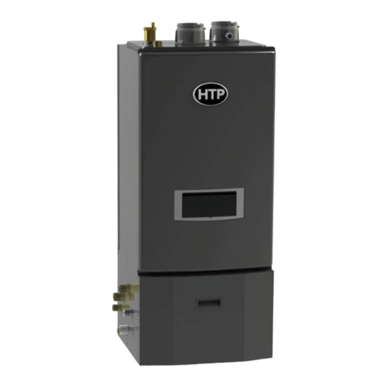
UFTC-140 / 199* Models
* "F" Denotes Floor Model; "W" Denotes Wall Mount Model, "LP" Denotes Propane Gas
This manual must only be used by a qualified service technician. Read all instructions in this manual before installing. Perform
steps in the given order. Failure to do so could result in substantial property damage, severe personal injury, or death.
Improper installation, adjustment, alteration, service, or maintenance could void product warranty and cause property
damage, severe personal injury, or death.
California Proposition 65 Warning: This product contains chemicals known to the State of California to cause cancer, birth
defects, or other reproductive harm.
The manufacturer reserves the right to make product changes or updates without notice and will not be held liable for
typographical errors in literature.
The surfaces of these products contacted by potable (consumable) water contain less than 0.25% lead by weight as required
by the Safe Drinking Water Act, Section 1417.
NOTE TO CONSUMER: PLEASE KEEP ALL INSTRUCTIONS FOR FUTURE REFERENCE.
272 Duchaine Blvd.
Universal Fire Tube
This Manual For Use With Boilers Manufactured On or After January 1, 2020
DANGER
!
WARNING
!
NOTICE
New Bedford, MA 02745
Floor and Wall Mount
Combi Boilers
Heat Exchanger Bears the
ASME "H" Stamp
www.htproducts.com
LP-648 Rev. 002 Rel. 002 Date 9.16.20
Advertisement
Table of Contents

Subscribe to Our Youtube Channel
Related Manuals for HTP UFTC-140


Summary of Contents for HTP UFTC-140
- Page 1 Start-Up Maintenance Parts Warranty UFTC-140 / 199* Models * “F” Denotes Floor Model; “W” Denotes Wall Mount Model, “LP” Denotes Propane Gas This Manual For Use With Boilers Manufactured On or After January 1, 2020 Heat Exchanger Bears the ASME “H” Stamp DANGER This manual must only be used by a qualified service technician.
- Page 2 WARNING WARNING: If the information in these instructions is not followed exactly, a fire or explosion may result causing property damage, personal injury or death. • Do not store or use gasoline or other flammable vapors and liquids in the vicinity of this or any other appliance. WHAT TO DO IF YOU SMELL GAS •...
- Page 3 Foreword This manual is intended to be used in conjunction with other literature provided with the boiler. This includes all related control information. It is important that this manual, all other documents included in this system, and additional publications including the National Fuel Gas Code - ANSI Z223.1 (latest versions), be reviewed in their entirety before beginning any work.
-
Page 4: Table Of Contents
In accordance with Section 325 (f) (3) of the Energy Policy and 1. Boilers generating a glow, spark or flame capable of igniting Conservation Act, HTP, Inc. has provided this boiler with multiple flammable vapors may be installed in a garage, provided the... -
Page 5: Part 1 - General Safety Information
D. Piping the Boiler Part 1 - General Safety Information E. Applications F. CH and DHW Pressure Relief Valves This boiler is approved for indoor installations only and is not intended Part 5 - Venting for use as a pool heater. Clearance to combustible materials: 0” top, A. -
Page 6: Improper Combustion
DO NOT alter or modify the boiler or boiler controls. Altering any Keep the area around the boiler clean and free of all materials that HTP, Inc. boiler with parts not manufactured by HTP, Inc. WILL can burn. DO NOT store or place gasoline, oils, spray paint, or other INSTANTLY VOID the boiler warranty and could result in property flammable products near the boiler. -
Page 7: When Servicing The Boiler
discontinue use of the boiler and contact an authorized technician or D. When Servicing the Boiler licensed professional. WARNING Contaminant Maximum Allowable Level Be sure to disconnect electrical power before opening boiler Total Hardness 200 mg/l (Residential Use - Below 140 F water cabinet or performing service. -
Page 8: Water Temperature Adjustment And Scalding
H. Water Temperature Adjustment and Scalding This boiler can deliver scalding water. Be careful whenever using water to avoid scalding injury. Certain boilers such as dishwashers and automatic clothes washers require increased water temperatures. By setting the thermostat on this heater to obtain increased water temperature required by... -
Page 9: Part 2 - Before You Start
Other Optional Equipment • 4” Stainless Steel Outside Termination Vent Kit (Part # V2000) Below is a list of other optional equipment available from HTP. These • 6” Stainless Steel Outside Termination Vent Kit (Part # V3000) additional options may be purchased through your HTP distributor: •... -
Page 10: Part 3 - Prepare The Boiler Installation
• 2” Mesh Vent Screens (Part # 7850P-088) CAUTION NOTE: When using an optional system sensor, pipe insulation must be wrapped around it to improve temperature measurement The service life of the boiler’s exposed metallic surfaces, such as accuracy and increase overall system efficiency. the casing, as well as internal surfaces, such as the heat exchanger, are directly influenced by proximity to damp and salty marine Part 3 - Prepare the Boiler Installation... -
Page 11: Residential Garage And Closet Installations
CAUTION All boilers eventually leak. Locate the boiler where any leakage from the relief valve, related piping, tank, or connections will not result in damage to surrounding areas or lower floors of the building. Any boiler should be installed in such a manner that if it should leak the resulting flow of water will not cause damage to the area in which it is installed. -
Page 12: Direct Vent Of Exhaust And Intake
WARNING CAUTION Do not attempt to vent this appliance by any means other than When drawing combustion air from the outside into the mechanical those described in this manual. Doing so will void the warranty room, care must be taken to provide adequate freeze protection. and may result in severe personal injury or death. -
Page 13: Removing A Appliance From A Common Vent System
Products to Avoid Areas Likely to Have Contaminants Spray cans containing fluorocarbons Dry cleaning / laundry areas and establishments Permanent wave solutions Swimming pools Chlorinated waxes / cleaners Metal fabrication plants Chlorine-based swimming pool chemicals Beauty shops Calcium chloride used for thawing Refrigeration repair shops Sodium chloride used for water softening Photo processing plants... -
Page 14: Technical Specifications
3.5 Gallons Minimum Flow Rate 0.5 GPM Total Water Capacity 5 Gallons Control Panel / Main Controller NGTX-900C / P-920C_CB-HTP CH Water Pressure Min 12 - Max 30 PSI DHW Water Pressure Max 150 PSI DHW Inlet / Outlet 3/4” NPT... - Page 15 BOTTOM Figure 3 - Wall Mount Model Dimensions Description Diameter Automatic Air Vent Air Intake Adapter 3” Exhaust Vent Adapter Pressure Relief Valve Adapter 3/4” NPTF CH Supply Adapter 1” NPT CH Return Adapter DHW Outlet Adapter DHW Inlet Adapter 3/4”...
- Page 16 Figure 4 - Floor Model Dimensions Model 17.3 19.1 16.8 44.8 12.6 13.5 19.7 21.5 18.2 13.3 10.8 15.1 Table 11 - Floor Model Specifications and Dimensions System Safeties – The boiler is provided with many safety features to connect the incoming gas supply. to ensure reliable and safe operation.
-
Page 17: Wall-Mounting (Wall Mount Models Only)
Figure 5 - Components Number Component Description Number Component Description Number Component Description Air Vent CH Return Adapter Control Panel Relief Valve Adapter CH Pressure Gauge Heat Exchanger Air / Gas Mixing Pipe DHW Outlet Adapter Ignition Transformer Gas Valve Gas Inlet Adapter Flame Detecting Sensor DHW Inlet Adapter with Filter and... -
Page 18: Flow Restrictor
WARNING This boiler is too heavy for one person to lift. It is highly recommended to install the boiler with two people. Use caution as to not drop the boiler, which could damage the boiler and cause property damage and/or severe personal injury. Verify that the boiler is properly and securely mounted before leaving unsupervised. -
Page 19: Part 4 - Water Piping
Figure 8 - Water Pressure vs. Flow through the Restrictors - 140 Models Figure 9 - Water Pressure vs. Flow through the Restrictors - 199 Models Part 4 - Water Piping WARNING A. General Plumbing Guidelines CAUTION Failure to follow the instructions in this section WILL VOID the warranty and may result in property damage, severe personal Use two wrenches when tightening water piping at the boiler. -
Page 20: Backflow Preventer
A shut off valve between the city water supply and preventer or any type of a no return valve in the system, install an DHW inlet is recommended for ease of service. HTP offers threaded additional tee here, suitable for an expansion tank. -
Page 21: Applications
E. Applications Figure 10 - Piping Symbol Legend LP-648 Rev. 002 Rel. 002 Date 9.16.20... - Page 22 Figure 11 - Primary / Secondary Piping with Zone Valves - DHW Priority and Outdoor Reset NOTES: 1. This drawing is meant to show system piping concept only. Installer is responsible for all equipment and detailing required by local codes. 2.
- Page 23 Figure 12 - Primary / Secondary Piping with Pumps - DHW Priority and Outdoor Reset NOTES: 1. This drawing is meant to show system piping concept only. Installer is responsible for all equipment and detailing required by local codes. 2. All closely spaced tees shall be within 4 pipe diameters center to center spacing. 3.
- Page 24 Figure 13 - Primary / Secondary Piping with Pumps - DHW Priority and Outdoor Reset with Recirculation NOTES: 1. This drawing is meant to show system piping concept only. Installer is responsible for all equipment and detailing required by local codes. 2.
- Page 25 Figure 14 - Primary / Secondary Piping with Pumps - DHW Priority and Outdoor Reset with Recirculation and Boiler Primary Pump NOTES: 1. This drawing is meant to show system piping concept only. Installer is responsible for all equipment and detailing required by local codes. 2.
- Page 26 Figure 15 - Primary / Secondary Piping with Pumps - DHW Priority and Outdoor Reset - Floor Model NOTES: 1. This drawing is meant to show system piping concept only. Installer is responsible for all equipment and detailing required by local codes. 2.
- Page 27 Figure 16 - Primary / Secondary Piping with Pumps - DHW Priority and Outdoor Reset with Recirculation and Boiler Primary Pump - Floor Model NOTES: 1. This drawing is meant to show system piping concept only. Installer is responsible for all equipment and detailing required by local codes. 2.
-
Page 28: And Dhw Pressure Relief Valves
(Heating Boilers). The included 30 psi CH Pressure Relief Valve must be installed on the CH supply line to ensure a compliant installation and safe operation. HTP has supplied a ¾” X 1” bushing to aid installation of the CH Pressure Relief Valve. The valve is meant to be field installed. -
Page 29: Part 5 - Venting
Part 5 - Venting DANGER The boiler must be vented as detailed in this section. Ensure exhaust vent and intake piping complies with these instructions regarding vent system. Inspect finished exhaust vent and intake piping thoroughly to ensure all joints are well secured, airtight, and comply with all applicable code requirements, as well as the instructions provided in this manual. -
Page 30: Approved Materials For Exhaust Vent And Intake Pipe
B. Approved Materials for Exhaust Vent and Intake Pipe Standards for Installation In: Item Material United States Canada Pipe and Fittings Approved for Intake ONLY ABS* ANSI/ASTM D2661 ANSI/ASTM D2661 PVC Schedule 40/80 UL-1738 or ANSI/ASTM D1785 PVC-DWV Schedule 40/80 UL-1738 or ANSI/ASTM D2665 UL-1738 or ULC-S636 Pipe Approved for... -
Page 31: Exhaust Vent And Intake Pipe Location
D. Exhaust Vent and Intake Pipe Location INSIDE CORNER DETAIL FIXED OPERABLE CLOSED FIXED CLOSED OPERABLE LP-179-CC 03/28/17 Exhaust Vent Terminal Intake Pipe Terminal Area Where Intake Terminal Is Not Permitted Figure 18 - Exit Terminals for Direct Vent Systems - ANSI Z223.1 / NFPA 54 for US and CAN/CSA B149.1 for Canada DESCRIPTION CANADA Clearance above grade, veranda, porch, deck, or balcony... -
Page 32: Exhaust Vent And Intake Pipe Sizing
NOTE: Clean and dry the boiler connection. DO NOT use primer or E. Exhaust Vent and Intake Pipe Sizing cement on the boiler connection. 1. The exhaust vent and intake pipe size is 3”. Push the length of pipe into the connection until it touches 2. -
Page 33: Applications
10. The exhaust vent must terminate where vapors cannot make This table lists optional exhaust/intake terminations available from accidental contact with people or pets, or damage shrubs or plants. HTP: 11. In vacant chimney applications, install and seal a rain cap over Description Stock Code existing chimney openings. - Page 34 Two Pipe Sidewall Venting Two Pipe Roof Venting EXTERIOR WALL with Elbow (Intake) with Elbow (Intake) and Coupling (Exhaust) and Coupling (Exhaust) 1" MIN. 12" MIN. EXHAUST INSERT EXHAUST SCREEN MAINTAIN 12" MINIMUM CLEARANCE ABOVE HIGHEST ANTICIPATED SNOW LEVEL OR GRADE, WHICHEVER IS GREATER (TYP) LP-505-A 06/23/15...
- Page 35 EXHAUST AIR INTAKE FRONT VIEW EXHAUST AIR INTAKE LP-325-PP 03/31/11 SIDE VIEW Figure 23 - Horizontal (Snorkel) Venting NOTES: A. For every 1” of overhang, the exhaust vent must be located 1” vertical below overhang (overhang means top of building structure and not two adjacent walls [corner of building]).
-
Page 36: Venting Through An Existing System
NOTE: The following instructions refer only to venting through an venting demonstration. existing vent system, and not to venting with HTP’s optional concentric vent kits. Refer to Concentric Vent Kit installation manual (LP-166) for Chase Venting through an Existing System... -
Page 37: Power Venting, Indoor Combustion Air In Confined Or Unconfined Space
3. Power Venting, Indoor Combustion Air in Confined or Unconfined Space This appliance requires fresh, uncontaminated air for safe operation with doors, are considered part of the space. Confined space is space with volume less than 50 cubic feet per and must be installed in a mechanical room where there is adequate combustion and ventilating air. -
Page 38: Part 6 - Installing The Condensate Drain
The condensate pump should (p/n 7450P-212 available from have an overflow switch to prevent property damage from spillage. HTP). Follow all the installation Condensate from the boiler will be slightly acidic (pH from 3.2 to instructions included with the 4.5). -
Page 39: Part 7 - Connecting Electrical Service
Part 7 - Connecting Electrical Service 1. This boiler must be properly grounded. Ensure the electrical WARNING receptacle is properly grounded. Do not remove the grounding prong from the boiler plug. Install wiring and electrically ground boiler in accordance with 2. - Page 40 Figure 33 - Electrical Wiring Diagram LP-648 Rev. 002 Rel. 002 Date 9.16.20...
- Page 41 Figure 34 - Ladder Diagram LP-648 Rev. 002 Rel. 002 Date 9.16.20...
- Page 42 Connector Description HT Selv No. of Location Board Silk GROUND Power Supply Line External CH Pump Power Supply (Live) Ignitor Power Supply L/(HT) Internal Pump Power Supply (Live) 65001WS-12 Gas Valve Power Supply HT (120V~) AC Power Supply (Neutral) 9-12 AC Power COM Line CP2/3WAY 3 Way Valve...
- Page 43 Connector Description HT SELV No. of Location Board Silk Flame Sensor OP.S Operating Water Temperature Sensor DH.S DHW Temperature Sensor NOT USED SELV (5V) LWD1140-14 BG.S Exhaust Temperature Sensor ST.S NOT USED SP.S Overheat Temperature Sensor DHM Stepper Motor Position DHM Stepper Motor Coil X Phase SELV (14V) CN14...
-
Page 44: Part 8 - Gas Connections
Part 8 - Gas Connections WARNING FIRE AND/OR EXPLOSION HAZARD To avoid serious injury or death, the gas line installation and the gas line inlet pressure test must be done by a licensed professional. Ensure the gas on which the boiler will operate is the same type specified on the rating plate (natural gas or LP gas). This boiler must be converted into propane operation unless specifically manufactured for use with propane. -
Page 45: Additional Precaution For Excess Flow Valve (Efv)
WARNING C. Additional Precaution for Excess Flow Valve (EFV) If an excess flow valve (EFV) is in the gas line, check the manufacturer’s minimum and maximum flow capacity ratings. An improperly sized It is required to use a calibrated combustion analyzer to verify final EFV will not allow for a full flow of gas to the boiler and will cause the adjustment according to the combustion chart (Table 25). -
Page 46: Part 9 - Controls
Part 9 - Controls A. Control and Display Overviews Figure 40 - Control Panel Detail Figure 41 - LCD Display After start-up, the display appears as follows. The LCD display also features a backlit lamp that will illuminate: • When a user action is detected (a button is pressed) •... -
Page 47: Changing The Dhw Set-Point
C. Changing the DHW Set-Point Press the button when the display panel is powered ON to change the DHW Set-Point. The display will appear as follows. Figure 44 - CH Set-Point Screens Factory CH Set-Point is 180 F (82 C). Initial CH Set-Point range is 86 – F (30 –... -
Page 48: Status Display
H. Status Display Status Display will activate when button is pressed and held for five seconds at Standby Mode when the display panel is powered ON. Figure 46 - Status Display Screens Display Display Detail Description (Main Menu) (Sub Menu) Current Outdoor Sensor Temperature O:ot Outdoor Temperature... -
Page 49: Installer Mode
I. Installer Mode Installer Mode will activate when button is pressed and held for five seconds while the boiler display is powered Off. Figure 47 - Installer Mode Screens Display Default Detail Description 1:EH E0.00 Error history up to 10 Check ten most recent Error Codes (E0 - E9) 2:cE Clear Error History... -
Page 50: Outdoor Temperature Mode (Optional)
Display Default Detail Description Sets the minimum design supply temperature based on the maximum outdoor design temperature. Minimum supply temperature must be set 9 F above the 17:cL Minimum Supply Temperature maximum supply temperature. Range: 86 F (Maximum Supply Temperature - 9 Sets Maximum DHW Setpoint Temperature Maximum DHW Setpoint 18:dH... -
Page 51: 0-10 Volt Input
See Figure 48 to set your Outdoor Reset Curve. To check the CH Target Temperature while using Outdoor Temperature Mode, press the button while the boiler is operational and the display panel is powered on. Figure 48 - Outdoor Reset Curve - See Installer Mode for Curve Setting Descriptions K. -
Page 52: Part 10 - Troubleshooting
Part 10 - Troubleshooting A. Error Code When the boiler encounters an error, the display will flash “Er” followed by a numerical code. The boiler shall enter a soft lockout condition if the error is such that it can return to normal operation once the condition relieves itself (overheat conditions, NTC open or shorts, etc.). The boiler shall enter a hard lockout if the condition indicates something more serious (flame, ignition, condensate line, etc.) To clear a hard lockout Error Code, press the Power button. - Page 53 Error Code Error Code Possible Remedies Description This Error Code will go away when operating temperature decreases. If Error happens again: Return Temperature Er:31 1. Check return temperature sensor. Ensure connections are secure. Sensor Open or Short 2. Check return sensor resistance. If resistance is zero, replace the sensor. 3.
- Page 54 Error Code Error Code Possible Remedies Description This Error Code will go away when the condition is remedied. Mixing Valve Opera- If Error happens again: tion Error 1. Turn power OFF and ON at the main power switch internal to the boiler. Er:68 (Mixing Valve Stuck in 2.
-
Page 55: Error Tree Analysis
B. Error Tree Analysis 1. Flame Detection Figure 50 - Flame Detection Error Analysis Tree 2. Air Pressure Switch / Burner Overheat Limit / Condensate Block Switch Figure 51 - APS / Burner Overheat Limit / Condensate Block Switch Error Analysis Tree 3. -
Page 56: Suggested Corrective Actions
C. Suggested Corrective Actions Problem Possible Causes Possible Remedies 1. Is the plug on the power supply cord unplugged 1. Reset the plug. from the electrical outlet? 2. Reset the circuit breaker. No electrical power to the 2. Is electrical panel’s 10 Amp circuit breaker 3. - Page 57 Display Condition Diagnostic Possible Corrective Actions Ensure service switch and/or circuit Turn on service switch or circuit breaker to breaker to boiler is turned ON power boiler Troubleshoot and correct the power supply to Is there 120V at the service switch the manual switch Nothing appears on Is the ON/OFF switch inside the boiler...
-
Page 58: Part 11 - Start-Up
Part 11 - Start-Up CAUTION Thoroughly clean and flush any system that has used glycol before installing the boiler. Provide the customer with a material safety data sheet (MSDS) on the fluid used. A. Check / Control Water Chemistry CAUTION Chemical imbalance of the water supply may affect efficiency and cause severe damage to the boiler and associated equipment. -
Page 59: Freeze Protection (When Used)
C. Freeze Protection (When Used) WARNING WARNING Eliminate all system leaks. Continual fresh make-up water will reduce NEVER use automotive or standard glycol antifreeze. Do not use boiler life. Minerals can build up in the heat exchanger, reducing ethylene glycol made for hydronic systems. Use only freeze- heat transfer, overheating the heat exchanger and causing heat protection fluids certified by fluid manufacturer as suitable for exchanger failure. -
Page 60: Purge Air From Dhw System
Figure 54 - Bleeding the Internal Pump available from HTP (554200). This pump is equipped with two leads Run pumps as required to help bleed out all entrapped air. Some... -
Page 61: Part 12 - Installation Checklist
Part 12 - Installation Checklist Before Installing Is there enough space to ensure proper installation? Does installation location allow for proper service clearances? Are water and gas lines properly sized and set at proper pressures for the installation? Is boiler location as near the exhaust vent / intake pipe terminations as possible? Have combustible materials been cleared from the installation location? Is there a drain close to the boiler? Water Piping... -
Page 62: Part 13 - Maintenance
Start-Up, Adjust, and Test Has the boiler been started? If necessary, has the boiler gas valve been adjusted? Has the installation been customized per installation location requirements? Have all customized system parameters been tested? Has proper boiler operation been confirmed? Burner Flame Has the burner flame been checked? Have combustion values been verified with a calibrated combustion analyzer? - Page 63 • If you notice flue gas leaking from the opening, this indicates a dry condensate drain trap. If problem persists, contact a qualified service technician to inspect the boiler and condensate line and refill the condensate trap. • If applicable, check the condensate neutralizer and ensure it is full of condensate neutralizing marble chips.
- Page 64 pump outlet and the cold water inlet line to valve V4. Connect the 10. Turn on the gas valve. Turn on electrical power to the boiler and other hose (D2) to the circulation pump inlet and place the free end press the Power button to turn the boiler on.
- Page 65 Maintenance Report 6. Fill the condensate trap with fresh water prior to reassembly on the boiler. CAUTION 7. Install the condensate trap on the condensate hose from the heat exchanger. Use the hose clamp to secure the trap. Attach the In unusually dirty or dusty conditions, care must be taken to keep clear plastic hose onto the hose barb.
- Page 66 INSPECTION ACTIVITIES DATE LAST COMPLETED 1 st YEAR 2 nd YEAR 4 th YEAR* 3 rd YEAR PIPING Near boiler piping Check boiler and system piping for any sign of leakage. Leaking pipes could cause property damage. Make sure all piping is properly supported.
-
Page 67: Part 14 - Moving Adapters From Left To Right (Floor Models)
Part 14 - Moving Adapters from Left to Right (Floor Models) 1. It is recommended to do this procedure 6. Use a Phillips Head screwdriver to before the appliance is installed. However, secure the removed right side panel if appliance is installed, ensure the to the left side of the appliance water and gas are shut off and all stand with the eight (8) screws... - Page 68 B-23 B-10 15-1 15-2 18-1 B-10 15-4 15-3 16-1 15-5 15-6 16-2 15-7 15-8 B-27 B-13 Figure 61 - Cabinet Replacement Parts - 140 Floor and Wall Mount Models NUMBER DESCRIPTION PART NUMBER NUMBER DESCRIPTION PART NUMBER Exhaust Duct Assembly 7855P-002 Ignition Transformer 7855P-007...
- Page 69 Figure 62 - Water Piping Replacement Parts - 140 Floor and Wall Mount Models NUMBER DESCRIPTION PART NUMBER NUMBER DESCRIPTION PART NUMBER DHW Outlet Pipe 7855P-242 DHW Inlet Block Cap 7855P-283 36-1 1/2” Pipe Gasket 7855P-072 CH Return Block with Filter 7855P-248 36-2 P18 O-Ring...
- Page 70 Figure 63 - Heat Exchanger Replacement Parts - 140 Floor and Wall Mount Models NUMBER DESCRIPTION PART NUMBER NUMBER DESCRIPTION PART NUMBER Exhaust Pipe Assembly 7855P-237 Exhaust Pipe Gasket 7855P-351 Storage Tank Clamp 7855P-297 Storage Tank Bracket 7855P-298 Exhaust Temperature Sensor Clip 7855P-349 Air Vent 7855P-063...
- Page 71 Figure 64 - Combustion System Replacement Parts - 140 Floor and Wall Mount Models NUMBER DESCRIPTION PART NUMBER NUMBER DESCRIPTION PART NUMBER Burner Inlet Channel Gasket 7855P-370 Mixer Clamp 7855P-376 Burner Inlet Channel (with Damper) 7855P-367 1/2” Gas Pipe Gasket 7855P-221 79-1 Air Damper 4G...
- Page 72 Figure 65 - Cabinet Replacement Parts - 199 Floor and Wall Mount Models NUMBER DESCRIPTION PART NUMBER NUMBER DESCRIPTION PART NUMBER Exhaust Duct Assembly 7855P-002 Display Panel Bracket 7855P-413 15-1 Exhaust/Intake Duct Clamps (Φ100) 7855P-332 Ignition Transformer 7850P-271 15-2 Exhaust/Intake Gaskets 7850P-210 24-1 Ignition Transformer Bracket...
- Page 73 Figure 66 - Water Piping Replacement Parts - 199 Floor and Wall Mount Models NUMBER DESCRIPTION PART NUMBER NUMBER DESCRIPTION PART NUMBER DHW Outlet Pipe 7855P-275 DHW Inlet Block Cap 7855P-283 38-1 3/4” Pipe Gasket 7855P-073 DHW Inlet Adapter 7855P-203 38-2 P18 O-Ring 7855P-047...
- Page 74 Figure 67 - Heat Exchanger Replacement Parts - 199 Floor and Wall Mount Models NUMBER DESCRIPTION PART NUMBER NUMBER DESCRIPTION PART NUMBER Exhaust Temperature Sensor Flame Sensor 7855P-031 7855P-092 63-1 Exhaust Temperature Sensor O-Ring Flame Sensor Cover 7855P-357 Exhaust Temperature Sensor Clip 7855P-349 Heat Exchanger Assembly 7865P-029...
- Page 75 Figure 68 - Combustion System Replacement Parts - 199 Floor and Wall Mount Models NUMBER DESCRIPTION PART NUMBER NUMBER DESCRIPTION PART NUMBER Burner Inlet Channel 7855P-479 Air Intake Hose (Bottom Clamp) 7855P-429 Plastic Flapper 7865P-033 APS Hose Fitting 7855P-375 Fan Outlet Gasket 7855P-425 Gas Valve Assembly 7855P-431...
- Page 76 Figure 69 - Floor Model Replacement Parts Item # Description 140 Model 199 Model Item # Description 140 Model 199 Model Base Assembly, Floor Stand 7865P-001 7865P-002 Locknut - Electrical - 1/2” 7700P-002 Screw M5 x 12MM 7865P-023 Barb Fitting 1/2” 7100P-044 Anchor and Wall Bracket 7850P-084...
-
Page 77: Limited Warranty For Uftc Boilers
COVERAGE any reason whatsoever. A. During the first year after the original date of installation, HTP warrants 6. Any water damage arising, directly or indirectly, from any defect in the that it will repair or replace, at its option, any defective or malfunctioning boiler or component part(s) or from its use. - Page 78 (12 grains/gallon) temperature) During the claims process a product that must be replaced will be given a designation of either a) field scrap, or b) return to HTP. If the product must Total Hardness 120 mg/l be returned to HTP, the returned product must arrive at HTP within thirty...
-
Page 79: Notes
Notes LP-648 Rev. 002 Rel. 002 Date 9.16.20... -
Page 80: Customer Installation Record Form
Customer Installation Record Form The following form should be completed by the installer for you to keep as a record of the installation in case of a warranty claim. After reading the important notes at the bottom of the page, please also sign this document. Customer’s Name Date of Installation Installation Address...
Need help?
Do you have a question about the UFTC-140 and is the answer not in the manual?
Questions and answers