
Related Manuals for Sanyo CMH3172A


Summary of Contents for Sanyo CMH3172A
- Page 1 APPENDIX A INSTALLATION INSTRUCTIONS CMH1972A CMH2472A CMH3172A (II-852-6-4190-507-00-0)
-
Page 2: Table Of Contents
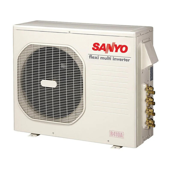
NOTE The illustrations are based on the typical appearance of a standard model. Consequently, the shape may differ from that of the air conditioner that you are installing. SANYO North America Corporation Commercial Solutions Division 2055 Sanyo Ave., San Diego CA 92154, U.S.A. -
Page 3: Important
Get a partner to help, and bend your knees when lifting to reduce strain on your back. Sharp edges or thin alu- minum fins on the air conditioner can cut your fingers. When Installing… …In a Ceiling or Wall Make sure the ceiling/wall is strong enough to hold the unit’s weight. -
Page 4: General
16. Vacuum pump (For R410A) 17. Manifold valve Q’ty Parts Figure CMH2472A Reducer (1/2" 3/8") CMH3172A Packed in the outdoor unit. Check local electrical codes CAUTION and regulations before obtaining wire. Also, check any specified instructions or limitations. Wide Tube Outer Dia. -
Page 5: Installation Site Selection
(rapid-start) fluorescent lamps. (These may prevent the air conditioner from receiving signals.) - Page 6 150 (L1+L2+L3) CMH2472A 150 (L1+L2+L3+L4) CMH3172A 150 (L1+L2+L3+L4) * If total tubing length becomes 150 to 200 ft. (Max.) or 150 to 230 ft. (Max.), charge additional refrigerant (R410A) by 0.22 oz./ft. No additional charge of compressor oil is necessary. For more detailed charging information, refer to the Technical & Service Manual.
-
Page 7: Connecting Indoor Units
2-2. Connecting Indoor Units Figures (4a) – (4k) show the different types of indoor unit connections, including the use of a reducer. To select the required indoor unit to be connected, refer to the Combination Table that was included in the outdoor unit package. - Page 8 Outdoor unit 1/2"(12.70mm) 1/4"(6.35mm) 3/8"(9.52mm) 1/4"(6.35mm) 3/8"(9.52mm) 1/4"(6.35mm) 3/8"(9.52mm) 1/4"(6.35mm) (1/2"(12.70mm) Flare 1/2"(12.70mm) Outdoor unit 1/2"(12.70mm) 1/4"(6.35mm) 3/8"(9.52mm) 1/4"(6.35mm) 3/8"(9.52mm) 1/4"(6.35mm) 3/8"(9.52mm) 1/4"(6.35mm) (3/8"(9.52mm) Locally purchased Flare 3/8"(9.52mm) Outdoor unit 1/2"(12.70mm) 1/4"(6.35mm) 3/8"(9.52mm) 1/4"(6.35mm) 3/8"(9.52mm) 1/4"(6.35mm) 3/8"(9.52mm) 1/4"(6.35mm) Indoor unit 1/2"(12.70mm) (KMHS1872) (XHS1872)
- Page 9 (3) Connecting indoor unit for CMH3172A (1/2"(12.70mm) Flare 1/2"(12.70mm) Outdoor unit 1/2"(12.70mm) 1/2"(12.70mm) 3/8"(9.52mm) 3/8"(9.52mm) (1/2"(12.70mm Flare 1/2"(12.70mm) Outdoor unit 1/2"(12.70mm) 1/2"(12.70mm) 1/4"(6.35mm) 3/8"(9.52mm) 1/4"(6.35mm) 3/8"(9.52mm) 1/4"(6.35mm) Outdoor unit 1/2"(12.70mm) 1/4"(6.35mm) 1/2"(12.70mm) 1/4"(6.35mm) 3/8"(9.52mm) 1/4"(6.35mm) 3/8"(9.52mm) 1/4"(6.35mm) 3/8"(9.52mm)) Supplied Reducer Union 3/8"(9.52mm)
- Page 10 (1/2"(12.70mm) Flare 1/2"(12.70mm) Outdoor unit 1/2"(12.70mm) 1/4"(6.35mm) 1/2"(12.70mm) 1/4"(6.35mm) 3/8"(9.52mm) 1/4"(6.35mm) 3/8"(9.52mm) 1/4"(6.35mm) Flare 1/2"(12.70mm) Union 3/8"(9.52mm) (1/2"(12.70mm) (1/2"(12.70mm) Flare 1/2"(12.70mm) Outdoor unit 1/2"(12.70mm) 1/4"(6.35mm) 1/2"(12.70mm) 1/4"(6.35mm) 3/8"(9.52mm) 1/4"(6.35mm) 3/8"(9.52mm) 1/4"(6.35mm) 5/8"(15.88mm))Locally purchased Union 5/8"(15.88mm) Indoor unit 5/8"(15.88mm) (KMHS2472) 3/8"(9.52mm) (KMHS0772,KMHS0972,KMHS1272) (XMHS0972,XMHS1272) 3/8"(9.52mm)
-
Page 11: Outdoor Unit
(Fig. 5f) This unit is designed so that the fan of the outdoor unit runs at low speed when the air conditioner is operated at low outdoor air temperatures. When the outdoor unit is exposed to strong wind, the system pressure drops because of the freeze protector. - Page 12 Fig. 5g For Air Intake Dimensions Model (inch) 25-3/16 25/32 1-31/32 CMH1972A, CMH2472A (mm) (inch) 25-3/16 25/32 CMH3172A (mm) For Air Discharge Dimensions Model (inch) 22-1/16 23-1/32 13-25/32 5-29/32 19-9/32 1-3/8 CMH1972A, 2472A, 3172A (mm) Material to be used: Metal plate with corrosion protection treatment Plate thickness: 0.0394 to 0.0472"...
-
Page 13: Installation Procedure
(3) Installation procedure 1. Air Intake Baffle (1) Left side 1. Remove the top panel from the unit. 2. Remove the panel side L, and drill 3 holes of ø1/4 inch (6.5 mm) at the prescribed position. 3. Install the windbaffle on the unit using field supply bolts and nuts. -
Page 14: Outer Dimensions Of Outdoor Unit
2-5. Outer Dimensions of Outdoor Unit (1) CMH1972A 23-15/16 5-11/32 15/32 (2) CMH2472A 23-15/16 5-11/32 15/32 (3) CMH3172A 23-15/16 5-11/32 15/32 35-7/16 (900) 2-29/32 2-1/32 1-13/16 2-1/16 Fig. 6a 35-7/16 (900) 2-29/32 1-13/16 2-1/32 2-1/16 2-13/32 Fig. 6b 35-7/16 (900) -
Page 15: Diagram Of Outdoor Unit Installation
Diagram of Outdoor Unit Installation 2-6. Never install only a single indoor unit. Be sure to connect indoor and outdoor units only in combinations that are listed in the catalog or in the combination table that was provided with the outdoor unit. (Use caution. -
Page 16: Installation Process
3. Installation Process Embedding the Tubing and Wiring 3-1. Do not connect tubes to locations that are embedded. Be sure to bind refrigerant tubing and inter-unit cables together with vinyl tape. The power cable must be obtained on-site. (#12: Less than 85 ft.) # ... -
Page 17: Caution Before Connecting Tubes Tightly
NOTE When reaming, hold the tube end downward and be sure that no copper scraps fall into the tube. (Fig. 9) (3) Remove the flare nut from the unit and be sure to mount it on the copper tube. (4) Make a flare at the end of copper tube with a flare tool.* (Figs. -
Page 18: Insulation Of Refrigerant Tubing
Be sure to match refrigerant CAUTION tubing and electric wiring between indoor and outdoor units. 3-6. Insulation of Refrigerant Tubing IMPORTANT To prevent heat loss and wet floors due to dripping of con- densation, both tubes must be well insulated with a proper insulation material. -
Page 19: Taping The Tubes
(special for R410A) With push-pin Fig. 20 In order to prevent charging errors CAUTION with the air conditioner that uses R410A, the screw diameter at the service valve charging port has been changed. When recharging or performing other servicing, use the special charging hose and manifold gauge. - Page 20 Perform the air purge for tubes A, B, C, and D. Use the same procedures for all tubes. (1) Check that each tube (both narrow and wide tubes) between the indoor and outdoor units have been proper- ly connected and all wiring for the test run has been completed.
-
Page 21: I Pump Down
(12) Test run the air conditioner. (See page 25.) (13) While the air conditioner is running, apply liquid soap to check for any gas leaks around the service valves or caps. (14) If there is no leakage, stop the air conditioner. -
Page 22: Wiring Instructions
Refer to your local codes or in the absence of local codes see the National Electric Code: ANSI/NFPA70. Table 6 Max. Power Line Length (ft.) Model CMH1972A CMH2472A CMH3172A Max. Control Line Length (ft.) (B) (C) (#12) (#14) 85 (Max.) 82 (Max.) 85 (Max.) -
Page 23: Wiring System Diagram
NOTE Disconnect switch may be required by national or local codes. Always comply with national and local code requirements. (2P) WARNING CAUTION 4 indoor units with CMH2472A, CMH3172A Disconnect switch Field supply 230/208V OUTDOOR UNIT 230/208V Terminal ( 12P ) -
Page 24: How To Connect Wiring To The Terminal
5-4. How to Connect Wiring to the Terminal Loose wiring may cause the WARNING terminal to overheat or result in unit malfunction. A fire hazard may also exist. There- fore, be sure all wiring is tightly connected. When connecting each power wire to the corresponding terminal, follow the instructions “How to connect wiring to the terminal”... -
Page 25: Wiring Instructions For The Outdoor Unit
Use a dedicated air conditioner circuit for power. To make connections to the outdoor unit, remove the inspection panel and tubing panel. Do not bring the inter-unit cables or power cable into contact with tubing or service valves. -
Page 26: Test Run
Regulations on wire size differ from locality to locality. For field wiring requirements, please refer to your local electri- cal codes. Make sure that the installation fully complies with all local and national regulations. (1) Remove access panel “C”. (Fig. 32) (2) Connect the inter-unit and power supply line accord- ing to the drawing on the panel side. -
Page 27: Sanyo
8. Installation Check Sheet The strength of the installation location is sufficient to support the air conditioner weight. The indoor and outdoor units are installed level and vertically. The power and voltage are as specified.
Need help?
Do you have a question about the CMH3172A and is the answer not in the manual?
Questions and answers