
Related Manuals for Rosen XR1020U


Summary of Contents for Rosen XR1020U
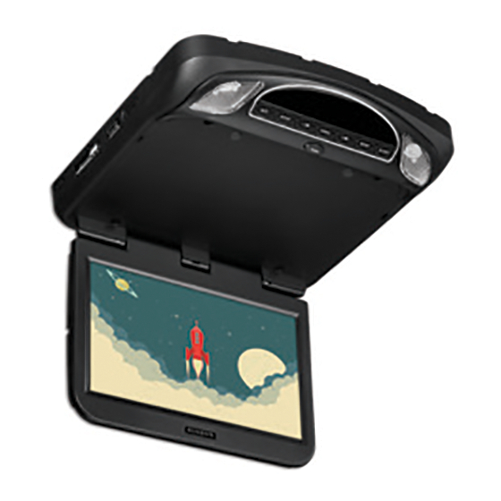
- Page 1 XR1020U 10.1” Vehicle Entertainment System Installation Guide PLA Y STOP EJECT PUSH...
- Page 3 Important Notices Installation of an Overhead Video Systems requires careful planning and preparation. Be extremely careful when working on a vehicle with side curtain air bags. Do not route wires near any portion of the side curtain air bag assemblies. This includes any anchor points in A, B, C or D pillars of the vehicle.
- Page 4 For safety reasons, when changing DVD based video media, it is recommended that the vehicle is not in motion, and that you do not allow children to unfasten seat belts to change DVD’s or make any adjustments to the system. System adjustments can be performed by using the remote control, while seat belts remain fastened.
-
Page 5: Table Of Contents
Table Of Contents Materials Included In This Package ............6 Installing The Unit In A Vehicle ..............8 Installing The Snap-On Shroud ..............9 Installing The Snap-On Screen Cover ............10 Installing The Trim Ring ................11 General Vehicle Installation Approach ..........12 Vehicle Preparation ..................13 Connecting The Dome Lights ..............14 Installing The Mounting Bracket .............16 Installing the System - Wiring Diagram ..........17... - Page 6 Materials Included In This Package HDH12 (Optional) WM1(Optional) 1. 10.1” Vehicle Entertainment System - (1 pc) 2. Hardware Package (P/N 540-017) - (1 pkg) M3 x 5mm Phillips Screws - (12 pcs) #8 x 3/8” Self Drilling Screws - (4 pcs) M5 x 10mm Phillips Screws - (4 pcs) M5 x 20mm Phillips Screws...
- Page 7 Materials Included In This Package CAUTION: The 10mm, 20mm and 40mm screws in the hardware kit are provided to facilitate installation of the monitor to the supplied bracket. Use extreme caution when using these screws to avoid damage to vehicle roof or other components, wiring, etc. 3.
-
Page 8: Installing The Unit In A Vehicle
Installing the Unit In A Vehicle Tools Required #2 Phillips Screwdriver #1 Phillips Screwdriver Utility or Razor Knife Wire Strippers Upholstery removal tools (for removal of panels and pillars as necessary) Electrical Tape Masking Tape Multimeter to verify 12 volt DC and continuity (Do not use a test light or logic probe) Marker pen –... -
Page 9: Installing The Snap-On Shroud
Installing the snap-on shroud Installing the Shroud *NOTE: Work on a soft surface to avoid damaging the plastic. 1. Remove the double sided tape backing from the two strips on the center section of the shroud. 2. Hook the shroud over the dome lights (front of system) and align the shroud tabs (1) with the eight openings around the rim of the system (2). -
Page 10: Installing The Snap-On Screen Cover
Installing the Snap-On Screen Cover Installing the Screen Cover 1. Open the LCD screen. 2. Hook the two tabs “A” (as shown) on the bottom edge of the screen. 3. Carefully snap the opposite side over the hinge. NOTE: If the wrong color Shroud and Screen Cover is installed, refer to Appendix A of this manual for instructions to change the Shroud and Screen Cover color. -
Page 11: Installing The Trim Ring
Installing the Trim Ring The trim ring is attached to the System using the perimeter screw bosses. It is important that the screws used in this installation are not over tightened, and that the video monitor and trim ring are mounted in such a way that the assembly does not distort (or bend) when the mounting screws are tightened. -
Page 12: General Vehicle Installation Approach
General Vehicle Installation Approach 1. 1. Decide upon the system configuration and peripheral options that will be installed with the system (ie...optional WM1 - SmartStream Module or HDH12 - 12’ HDMI/USB extension harness for remote connectivity of Smartphones or SmartTV devices). 2. -
Page 13: Vehicle Preparation
Vehicle Preparation 1. Locate an accessory +12v power source with a good ground. These wires can be found at the ignition switch or fuse-box. Power Source • +12v when the key is in the ACC and RUN positions. • 0v when the key is OFF. NOTE: Always fuse the ACC +12V at the source where it is connected to the vehicle. -
Page 14: Connecting The Dome Lights
Connecting the Dome Lights The dome lights in the System require three connections to the vehicle’s wiring. There are two common types of dome light circuits used, positive switched systems or negative switched systems. Positive switched systems supply voltage to the dome lights to turn them ON. - Page 15 Connecting the Dome Lights Positive Switched Dome Lighting Negative Switch Red/Black-Lamp on To 3 pin Red/Black-Lamp ON To 3 pin Black/Red-Lamp com constant connector connector Black/Red-Lamp Common Purple/Brown-Lamp A +12 VDC on Monitor Purple/Brown-Lamp Auto Fused Factory Dome Light Circuit constant +12 VDC Factory Door Ajar...
-
Page 16: Installing The Mounting Bracket
Installing the Mounting Bracket Installing the Mounting Bracket 1. Once all the pre-wiring is complete, locate: • Mounting Bracket • (4) #8 x 3/8” Self-Drilling Screws 2. Carefully align the Mounting Bracket in the location it is to be installed with the direction arrow facing the front of the vehicle (make sure there is nothing between the Mounting Bracket and Roof Cross-Member). -
Page 17: Installing The System - Wiring Diagram
Installing the System - Wiring Diagram Connect the 6 pin harness to the unit and make the connections to the vehicle. Connect the red and black power wires of the Power Harness to vehicle’s electrical system by connecting into a stable accessory +12v feed and a good ground. Soldering all power connection is the suggested technique that should be used to ensure a problem free connection. - Page 18 Installing the System - Wiring Diagram Wiring Diagram WM1(Optional SmartStream Module) (P/N 600007) HDMI 2 (Optional Extension Harness HDH12) (103660) RF OUTPUT 5 Pin AV Input Harness (P/N 112-4259) 5 Pin AV Output Harness (P/N 112-4260) NOTE: The Hidden 24 Pin connector only allows connection of either optional SmartStream Module (WM1) or HD/USB Extension harness (HDH12).
-
Page 19: Installing The System - Mounting The Unit
Installing the System - Mounting the Unit Installing the System 1. Make all electrical connections. 2. Attach the Unit to the mounting bracket using four M5 screws. CAUTION: The M5 screws are supplied in three different lengths (10mm, 20mm and 40mm) to facilitate proper installation. -
Page 20: Appendix A - Removing The Screen Back Cover
Appendix A - Removing the Screen Back Cover This section is intended for situations where the color of the Shroud, Screen Cover and Trim Ring need to be changed after the unit is setup for installation. NOTE: Work on a soft surface to avoid damaging the plastic. Removing the Screen Back Cover 1. -
Page 21: Appendix A - Removing The Trim Ring And Shroud
Appendix A - Removing the Trim Ring and Shroud Removing the Trim Ring 1. Remove the Trim Ring screws ((8) M3 x 5mm screws). NOTE: Do not Discard Screws! These screws are used to attach the new Trim Ring. 2. Remove the Trim Ring and discard. (8)... -
Page 22: Appendix B- I Nstalling The Optional Smartstream Module (Wm1)
Appendix B - Installing the Optional SmartStream Module (WM1) This section is intended as an installation guide to connect the WM1 Module to the Unit NOTE: The WM1 Module is sold separately and is supplied with its own instruction manual. Installing the WM1 Module Turn the System over and place it on a surface with a protective covering to prevent scratches. -
Page 23: Troubleshooting
Troubleshooting SYMPTOM: REMEDY: No power at video monitor • Verify +12 VDC on the Red wire at 6 Pin Power/ Dome Light Harness behind the video monitor. Verify a ground connection with a continuity test from a known good ground to the black wire. Power but no video or sound • Verify that the Source is on and playing back compatible media content. - Page 24 Troubleshooting SYMPTOM: REMEDY: FM Transmitter does not work • Check if radio is ON and in FM mode. • Check that radio is tuned to the same frequency as the unit is set to. • Select another FM channel. • Reposition the Unit Wireless FM antenna for better reception.
- Page 28 www.voxxelectronics.com © 2019 Voxx Electronics Corp.,180 Marcus Blvd Hauppauge, NY 11788 730139...
Need help?
Do you have a question about the XR1020U and is the answer not in the manual?
Questions and answers