Advertisement
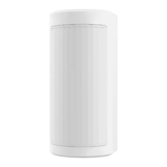
DS-PDP18-HM
Wired Double PIR Detector
User Manual
EN50131-2-2:2021
Security Grade 2
Environment Class IV
UD33808B
User Manual Flow Chart
2 Installation
1 Appearance
2.1 Confirm environment.
1.1 Unbox.
2.2 Fix the device (Wall
1.2 Check components.
mounting/Bracket mounting).
3 Connect to
Control Panel
Check the indicator,
Select the wiring type and
and the device is
connect the detector to the
powered on.
control panel.
Check detection range
in H and L mode.
1 Appearance
67.3 mm
2 Installation
Installation Environment
Facing Direct
Source of
Facing reflective
Strong Light
air currents
surfaces
Areas with
Surface that absorb heat or
moving objects
rapid temperature change area
Back of Wire hole
4
5. Fix the rear panel to the
4. Method 2: Thread the
corresponding position on the wall
cables through the wire
with two screws. Remove the wiring
hole on the rear panel.
terminal and finish wiring.
Hangzhou Hikvision Digital Technology CO.,Ltd. No.555 Qianmo Road, Binjiang District, Hangzhou 310052, China
60.0 mm
LED ON (default)
LED OFF
LED Jumper
PIR Sensitivity Jumper
Auto (default)
Pet Immunity
Tamper Switch
1 Wall Mounting
1
1. Adjust the knob to the
unlock icon.
Wire Terminal
5
6
6. Install the wiring terminal
back and fix the cables into
the wire slot.
Bracket Tamper
High and Low Mounting Adjustment Lever
H Model (default): 2.5 to 3 m (typical 2.7 m)
L Model: 0.8 to 1.2 m (typical 1 m)
2
3
2. Press the button.
4. Method 1 (Recommended):
Thread the cables through the
3. Remove the rear panel.
middle wire hole on the rear panel.
Wire Slot
7
7. Adjust the high and low
8. Adjust the knob to the lock icon.
mounting adjustment lever,
and Install the front panel.
4
8
Advertisement
Table of Contents

Summary of Contents for HIKVISION DS-PDP18-HM
- Page 1 Remove the wiring hole on the rear panel. terminal and finish wiring. the wire slot. and Install the front panel. in H and L mode. Hangzhou Hikvision Digital Technology CO.,Ltd. No.555 Qianmo Road, Binjiang District, Hangzhou 310052, China...
- Page 2 2 Bracket Mounting Wire Slot 5. Install the wiring terminal back and fix the 4. Install the bracket to the wall. 1. Adjust the knob to the 2. Press the button. cables into the wire slot. Thread the tamper unlock icon. 3.
- Page 3 3 Connect to Control Panel 4 Power on Note: The resistor needs to be connected to the end of detector. After powering on, the indicator flashes rapidly. Once the detector self test is completed, the LED indicator will go out until the detector detects movement. None Resistor Connection FAULT TAMPER...
- Page 4 5 Detection Range 6 Specification Top View Detection method Passive Infrared Detection range 18 m (16m EN certified) Detection angle 90° Detection zones Detection Detectable speed 0.3 to 2 m/s performance Sensitivity Auto, Pet White light filter 20000 lux Pet immunity Up to 24 Kg Digital temperature compensation Support...


Need help?
Do you have a question about the DS-PDP18-HM and is the answer not in the manual?
Questions and answers