Lennox SLP99UH070XV36B Manual
Hide thumbs
Also See for SLP99UH070XV36B:
- Installation instructions manual (70 pages) ,
- Unit information (84 pages)
Table of Contents
Advertisement
Service Literature
SLP99UHV series units are high-efficiency upflow, horizon
tal right and left) gas furnaces equipped with variable ca
pacity gas valve, variable speed combustion air inducer and
variable speed indoor blower motor. All models are de
signed only for direct vent (dual pipe) venting system.
SLP99UHV units are available in heating capacities from
66,000 to 132,000 Btuh (19.3 to 38.6 kW) and cooling ap
plications from 2 to 5 tons (7.0 kW to 17.5 kW). Refer to En
gineering Handbook for proper sizing.
Units are factory-equipped for use with natural gas. Kits are
available for conversion to LPG operation. SLP99UHV mod
®
els include a SureLight
variable capacity integrated control
that can be used with a Lennox communicating thermostat
as part of a communicating comfort system. All SLP99UHV
units meet the California Nitrogen Oxides (NO
and California Seasonal Efficiency requirements.
All specifications in this manual are subject to change. Pro
cedures outlined in this manual are presented as recom
mendations only and do not supersede or replace local or
state codes. In the absence of local or state codes, the
guidelines and procedures outlined in this manual (except
where noted) are recommendations only and do not consti
tute code.
TABLE OF CONTENTS
. . . . . . . . . . . . . . . . . . . . . . . . . . . . .
. . . . . . . . . . . . . . . . . . . . . .
. . . . . . . . . . . . . . . . . . . . . . . . . . . . . .
. . . . . . . . . . . . . . . . . . . . . . .
III Placement and Installation
. . . . . . . . . . . . . . . . . . . . . . . . . . . . . .
. . . . . . . . . . . . . . . . . . . . . . . . . .
VIII Wiring and Sequence of Operation
XI Field Wiring
. . . . . . . . . . . . . . . . . . . . . . . . . .
SLP99UHV SERIES UNITS
) Standards
x
Page 2
Page 3
Page 4
Page 20
. . . . . . . . . . . . . .
Page 44
. . . . . . . . . . . . . .
Page 47
Page 63
. . . . . . . . . .
Page 60
. . . . . . . .
Page 69
Page 70
. . . . .
Page 73
Page 81
Page 1
100001
10/2020
WARNING
Improper installation, adjustment, alteration, service
or maintenance can cause property damage, person
al injury or loss of life. Installation and service must
be performed by a licensed professional HVAC in
staller (or equivalent), service agency or the gas sup
plier.
Electric shock hazard. Can cause injury
or death. Before attempting to perform
any service or maintenance, turn the
electrical power to unit OFF at discon
nect switch(es). Unit may have multiple
power supplies.
CAUTION
As with any mechanical equipment, contact with
sharp sheet metal edges can result in personal injury.
Take care while handling this equipment and wear
gloves and protective clothing.
SLP99UHV
WARNING
© 2020 Lennox Industries Inc.
Advertisement
Chapters
Table of Contents

Related Manuals for Lennox SLP99UH070XV36B


Summary of Contents for Lennox SLP99UH070XV36B
-
Page 1: Table Of Contents
LPG operation. SLP99UHV mod ® els include a SureLight variable capacity integrated control that can be used with a Lennox communicating thermostat as part of a communicating comfort system. All SLP99UHV units meet the California Nitrogen Oxides (NO ) Standards and California Seasonal Efficiency requirements. -
Page 2: Specifications
SP ECIF ICATIONS Model No. SLP99UH070XV36B SLP99UH090XV36C SLP99UH090XV48C Heating AFUE 98.1% 98.1% 98.2% Performance Maximum Input - Btuh 66,000 88,000 88,000 Output - Btuh 64,000 85,000 85,000 Temperature rise range - °F 50 - 80 60 - 90 50 - 80 Gas Manifold Pressure (in. -
Page 3: Optional Accessories
OPT IONAL AC C ESSORIES - ORD ER SEPARAT ELY NOTE - FURNACES CANNOT BE TWINNED! “B” Width “C” Width “D” Width Models Models Models CABINET ACCESSORIES Horizontal Suspension Kit - Horizontal only 51W10 51W10 51W10 Return Air Base - Upflow only 50W98 50W99 51W00... -
Page 4: Blower Data
BLO WER DATA SLP99UH070XV36B BLOWER PERFORMANCE (less filter) BOTTOM RETURN AIR HEATING BLOWER PERFORMANCE - 0 through 0.8 in. w.g. External Static Pressure Range Heating Input Range and Blower Volume - CFM Heating Adjust CFM Selections 100% Increase (+15%) Heat CFM... - Page 5 BLOWER DATA SLP99UH070XV36B BLOWER PERFORMANCE (less filter) SINGLE SIDE RETURN AIR HEATING BLOWER PERFORMANCE - 0 through 0.8 in. w.g. External Static Pressure Range Heating Input Range and Blower Volume - CFM Heating Adjust CFM Selections 100% Increase (+15%) Heat CFM 1093 Increase (+7.5%) Heat CFM...
- Page 6 BLOWER DATA SLP99UH070XV36B BLOWER PERFORMANCE (less filter) SINGLE SIDE RETURN AIR WITH OPTIONAL RETURN AIR BASE HEATING BLOWER PERFORMANCE - 0 through 0.8 in. w.g. External Static Pressure Range Heating Input Range and Blower Volume - CFM Heating Adjust CFM Selections...
- Page 7 First stage COOL (two-stage air conditioning units only) is approximately 70% of the same second stage COOL speed position. Continuous Fan speeds are approximately 28% and 38% (DIP switch selectable) of the same second-stage COOL speed position. minimum 250 cfm. Lennox iHarmony Zoning System Applications - Minimum blower speed is 250 cfm. ®...
- Page 8 First stage COOL (two-stage air conditioning units only) is approximately 70% of the same second stage COOL speed position. Continuous Fan speeds are approximately 28% and 38% (DIP switch selectable) of the same second-stage COOL speed position. minimum 250 cfm. Lennox iHarmony Zoning System Applications - Minimum blower speed is 250 cfm. ®...
- Page 9 First stage COOL (two-stage air conditioning units only) is approximately 70% of the same second stage COOL speed position. Continuous Fan speeds are approximately 28% and 38% (DIP switch selectable) of the same second-stage COOL speed position. minimum 250 cfm. Lennox iHarmony Zoning System Applications - Minimum blower speed is 250 cfm. ®...
- Page 10 First stage COOL (two-stage air conditioning units only) is approximately 70% of the same second stage COOL speed position. Continuous Fan speeds are approximately 28% and 38% (DIP switch selectable) of the same second-stage COOL speed position. minimum 380 cfm. Lennox iHarmony Zoning System Applications - Minimum blower speed is 380 cfm. ®...
- Page 11 First stage COOL (two-stage air conditioning units only) is approximately 70% of the same second stage COOL speed position. Continuous Fan speeds are approximately 28% and 38% (DIP switch selectable) of the same second-stage COOL speed position. minimum 3808 cfm. Lennox iHarmony Zoning System Applications - Minimum blower speed is 380 cfm. ®...
- Page 12 First stage COOL (two-stage air conditioning units only) is approximately 70% of the same second stage COOL speed position. Continuous Fan speeds are approximately 28% and 38% (DIP switch selectable) of the same second-stage COOL speed position. minimum 380 cfm. Lennox iHarmony Zoning System Applications - Minimum blower speed is 380 cfm. ®...
- Page 13 First stage COOL (two-stage air conditioning units only) is approximately 70% of the same second stage COOL speed position. Continuous Fan speeds are approximately 28% and 38% (DIP switch selectable) of the same second-stage COOL speed position. minimum 380 cfm. Lennox iHarmony Zoning System Applications - Minimum blower speed is 450 cfm. ®...
- Page 14 First stage COOL (two-stage air conditioning units only) is approximately 70% of the same second stage COOL speed position. Continuous Fan speeds are approximately 28% and 38% (DIP switch selectable) of the same second-stage COOL speed position. minimum 380 cfm. Lennox iHarmony Zoning System Applications - Minimum blower speed is 450 cfm. ®...
- Page 15 First stage COOL (two-stage air conditioning units only) is approximately 70% of the same second stage COOL speed position. Continuous Fan speeds are approximately 28% and 38% (DIP switch selectable) of the same second-stage COOL speed position. minimum 380 cfm. Lennox iHarmony Zoning System Applications - Minimum blower speed is 450 cfm. ®...
- Page 16 First stage COOL (two-stage air conditioning units only) is approximately 70% of the same second stage COOL speed position. Continuous Fan speeds are approximately 28% and 38% (DIP switch selectable) of the same second-stage COOL speed position. minimum 380 cfm. Lennox iHarmony Zoning System Applications - Minimum blower speed is 450 cfm. ®...
- Page 17 First stage COOL (two-stage air conditioning units only) is approximately 70% of the same second stage COOL speed position. Continuous Fan speeds are approximately 28% and 38% (DIP switch selectable) of the same second-stage COOL speed position. minimum 380 cfm. Lennox iHarmony Zoning System Applications - Minimum blower speed is 450 cfm. ®...
- Page 18 First stage COOL (two-stage air conditioning units only) is approximately 70% of the same second stage COOL speed position. Continuous Fan speeds are approximately 28% and 38% (DIP switch selectable) of the same second-stage COOL speed position. minimum 380 cfm. Lennox iHarmony Zoning System Applications - Minimum blower speed is 450 cfm. ®...
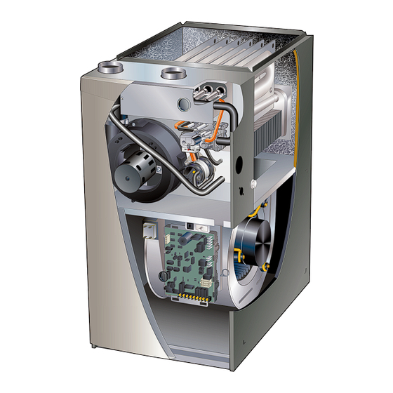
- Page 19 SLP99UHV PARTS ARRANGEMENT BURNER BOX ASSEMBLY PRESSURE SWITCHES HEAT EXCHANGER VARIABLE CAPACITY PRIMARY LIMIT GAS VALVE VARIABLE SPEED COMBUSTION AIR INDUCER BAG ASSEMBLIES (shipping location) COLD END HEADER ACCESS PANEL VARIABLE SPEED BLOWER MOTOR SIGHT GLASS INNER BLOWER ACCESS PANEL CONTROL BOX (includes variable capacity integrated control transformer circuit breaker and door switch)
-
Page 20: I Unit Components
4. Integrated Control (A92) An interlock switch rated 14A at 125VAC is wired in series ® SLP99UHV units are equipped with the Lennox SureLight with line voltage. When the inner blower access panel is re moved the unit will shut down. - Page 21 Electronic Ignition Three-Stage Timed Operation ® At the beginning of the heat cycle the SureLight integrated Using a single-stage thermostat the system will operate in a control monitors the low fire combustion air inducer pres three stage timed mode. Upon a call for heat and a success sure switch.
- Page 22 NEUTRAL TERMINALS COMBUSTION AIR INDUCER CONNECTOR IGNITOR CONNECTOR FLAME SENSE DIAGNOSTIC LINE VOLTAGE PUSH BUTTON TERMINALS DIP SWITCHES ON-BOARD LINKS OUTDOOR AIR INDOOR SENSOR BLOWER TERMINALS 7-SEGMENT CONNECTOR DIAGNOSTIC LED W915 Y1 TO Y2 DISCHARGE AIR SENSOR W951 R TO O TERMINALS W914 R TO DS FACTORY TEST...
- Page 23 SLP99UHV INTEGRATED CONTROL CONFIGURATION GUIDE FIGURE 5 Page 23...
- Page 24 TABLE 3 Thermostat Selection Switch Settings Operation Thermostat Switch 1 Switch 2 Switch 3 Variable Capacity Heat Two-Stage (35% to 100%) Three-Stage Heat Single-Stage 2nd stage delay (35%, 70%, 100%) OFF = 7 minutes ON = 12 minutes 3rd stage delay 10 minutes fixed Two-Stage Heat (W1 70%, W2 100%) Two-Stage...
- Page 25 Switches 10 and 11 -- Cooling Mode Blower Speed Ad Ramping Option A (Factory Selection) D Motor runs at 50% for 30 seconds. justment -- Switches 10 and 11 are used to select blower D Motor then runs at 82% for approximately 7-1/2 min speed adjustment settings.
- Page 26 TABLE 9 TABLE 10 Low Heat Blower Speeds High Heat Blower Speeds Blower Blower DIP SWITCH SETTINGS DIP SWITCH SETTINGS Thermostat Speed Thermostat Speed Demand Adjust Demand Adjust ments ments +15% +15% +7.5% +7.5% High Heat Low Heat (R to Normal Normal (R to W1)
- Page 27 On-Board Link W914 DS to R (Figure 4) While in the Field Test mode the technician can: D Initiate furnace ignition and move to and hold low-fire On-board link W914, is a clippable connection between ter minals DS and R on the integrated control. W914 must be rate by applying a R to W1 jumper.
- Page 28 TABLE 11 Idle Menu Options These options are displayed on the menu when the button is pressed during normal operation DISPLAY ACTION (when button released) No change (idle) remain in idle mode Solid “E” enter diagnostic mode Solid “-” enter field test mode NOTE - No change implies the display will continue to show whatever is currently being displayed for normal operation TABLE 12 Field Test Menu Options...
- Page 29 Configuring Unit Size Codes − − Power-Up - Number displayed represents by integrated control unit size code (furnace model − and capacity). If three horizontal bars are displayed followed by continuous E203, furnace control does not recognize unit size code. Configure per the following: Furnace control in IDLE mode No heating, cooling or indoor fan operation)
- Page 30 TABLE 14 LED 7 Segment Status / Error Code Press the diagnostic push button and hold it to cycle through a menu of options. Every five seconds a new menu item will be displayed. Release the button when the desired mode is displayed. When a solid ”P”...
- Page 31 Integrated Control Diagnostic Codes (continued) Code Diagnostic Codes/Status of Equipment Action Required to Clear and Recover E 202 Indoor blower motor mis-match - Indoor motor horsepower does not match unit Incorrect furnace size code selected. Check unit size capacity. codes on configuration guide or in installation instructions. E 203 Appliance capacity / size is NOT programmed.
- Page 32 Integrated Control Diagnostic Codes (continued) Code Diagnostic Codes/Status of Equipment Action Required to Clear and Recover E 292 Indoor blower motor unable to start - Seized bearings, stuck wheel, etc. Indoor blower motor unable to start (seized bearing, stuck wheel, etc), replace motor or wheel if assembly does not operate or meet performance.
- Page 33 TABLE 15 OPERATING SEQUENCE SLP99UHV and Single-Stage Outdoor Unit OPERATING SYSTEM DEMAND SYSTEM RESPONSE SEQUENCE Demand Relative Humidity Blower System Step Compressor Comments Condition Status (COOL) stage NO CALL FOR DEHUMIDIFICATION Compressor and indoor Normal Operation Acceptable High 100% blower follow thermostat demand BASIC MODE (only active on a Y1 thermostat demand) Normal Operation...
- Page 34 TABLE 16 OPERATING SEQUENCE SLP99UHV and Two-Stage Outdoor Unit OPERATING SYSTEM DEMAND SYSTEM RESPONSE SEQUENCE Demand Relative Humidity Blower System Comments Step Compressor Condition Status (COOL) stage stage NO CALL FOR DEHUMIDIFICATION Normal Operation - Acceptable Compressor and indoor blower follow thermostat Normal Operation - demand Acceptable...
- Page 35 DC filter capacitors inside the controller. If the discon nect switch is bounced when the disconnect is closed, the dis Earlier ECM motors used on other Lennox furnace models are not interchangeable with motors used on connect contacts may become welded. Try not to bounce the the SLP99UHV furnace line.
- Page 36 Motor Start‐Up Note: Do not apply 24V to pins 2 and 4 on P49. Doing so will cause permanent damage to the motor. When B3 begins start‐up, the motor gently vibrates back and forth for a moment. This is normal. During this time the elec 6- Motor should run at 75%.
- Page 37 Troubleshooting Motor Windings Ensure that motor windings are not damaged by performing the following tests: BLOWER B3 HARNESS CONNECTORS NOTE - If your ohm meter is not an auto-ranging type, set it to the highest ohm scale (100k ohms or greater) before per P48 5 Pin forming tests.
- Page 38 2 - Each lead-to-lead resistance should be the same. TABLE 18 Flame Signal in Microamps If the measured resistance is greater than 20 ohms, replace Normal Drop Out the motor and control module. 2.6 or greater 2.5 or less Test B NOTE - A much higher than normal micro amp reading (15 for example) may appear when checking flame signal.
- Page 39 Burner Box Assembly burner assembly intake air collar rollout switch flame sensor Cover plate (-090XV60C model only) ignitor burner box front cover (remove screw to open cover) sight glass FIGURE 14 Page 39...
- Page 40 Inlet and outlet pressure taps are located on the valve. is sensed in the heat exchanger, the limit will open. Once the LPG change over kits are available from Lennox. Kits include limit opens, the furnace control energizes the supply air burner orifices and an LP gas valve.
- Page 41 8. Combustion Air Inducer (B6) & Pressure Switch Combustion Air Inducer Troubleshooting (S18) S Is the CAI mounted correctly? All SLP99UHV units are equipped with a combustion air in S Any air or condensate leaks? ducer (B6) and dual pressure switch assembly (high fire and S Does the motor and wheel turn freely? low fire).
- Page 42 Vent Calibration After calibration, the integrated control stores the RPM1 and RPM2 values. The low fire (35%) and high fire (100%) The vent calibration sequence establishes furnace operat RPM points are calculated by adding margin values to the ing parameters in a specific installation. The integrated con RPM1 and RPM2 values.
- Page 43 Measuring Pressure Differential BLACK TUBING POSITIVE To Cold End Header Box Field Installed RED and BLACK TUBING or RED TUBING NEGATIVE Measuring Device Operate unit and observe measuring device reading. Remove thermostat demand and allow unit to cycle off. Readings will change as heat exchanger warms. Install a tee in the negative (-) line (red and black tubing or red a.
-
Page 44: Communicating Thermostat
II-Communicating Thermostat (if applicable) Refer to the illustrations provided with the thermostat for installation, set-up and operation. In communicating applications a communicating thermo stat must be used. In these applications the thermostat See figures 19 and 20 for thermostat wiring in communicat overrides the DIP switch settings on the integrated control. - Page 45 Optional Accessories for use with any Communicating System NOTE: THERMOSTAT SENSES HUMIDITY & CONTROLS 24V “H” OUTPUT (& 120V “H” OUTPUT) TO CYCLE HUMIDIFIER BASED ON DEMAND. NO OTHER CONTROL OR HUMIDISTAT REQUIRED. COMMUNICATING ENABLED FURNACE OPTIONAL OUTDOOR AIR SENSOR FOR USE WITH HUMID IFIER (IF NOT ALREADY IN THE SYSTEM FOR OTHER FUNCTIONS.
- Page 46 LENNOX COMMUNICATING OUTDOOR UNIT INDOOR UNIT (1 OR 2 STAGE) FLOAT SWITCH LENNOX COMMUNICATING OUTDOOR UNIT LENNOX COMMUNICATING FURNACE EL296V, SL280V, SL280VN, SL297V, SLP99V cutting DS to R will not cause communication interuption or error code CUT* R−DS W914 FIGURE 21...
- Page 47 III-PLACEMENT AND INSTALLATION CAUTION Pipe & Fittings Specifications Solvent cements for plastic pipe are flammable liq All pipe, fittings, primer and solvent cement must conform uids and should be kept away from all sources of igni with American National Standard Institute and the Ameri tion.
- Page 48 TABLE 22 OUTDOOR TERMINATION USAGE* STANDARD CONCENTRIC Flush Wall Kit Wall Ring Kit Mount 1-1/2 inch 2 inch 3 inch Vent 2 inch 3 inch 2 inch Pipe Input Size Field Dia. in. 51W11 71M80 69M29 Fabricated 44J40 22G44 (US) 60L46 (US) (US) (US)
- Page 49 Vent Piping Guidelines REPLACING FURNACE THAT WAS PART OF A COMMON VENT SYSTEM ® NOTE - Lennox has approved the use of DuraVent Centrotherm manufactured vent pipe and terminations as CHIMNEY ® an option to PVC. When using the PolyPro...
- Page 50 In some applications which permit the use of several differ Piping Size Process ent sizes of vent pipe, a combination vent pipe may be used. Contact Lennox' Application Department for assistance in What is the sizing vent pipe in these applications.
- Page 51 TABLE 24 Maximum Allowable Intake or Exhaust Vent Length in Feet NOTE - Size intake and exhaust pipe length separately. Values in table are for Intake OR Exhaust, not combined total. Both Intake and Exhaust must be same pipe size. NOTE - Additional vent pipe and elbows used to terminate the vent pipe outside the structure must be included in the total vent length calculation.
- Page 52 TYPICAL EXHAUSTAND INTAKE PIPE CONNECTIONS IN UPFLOW APPLICATIONS 2” EXHAUST 2” EXHAUST INTAKE INTAKE 2” 2” 2” 2” 3” 3” 070 Only 1−1/2” TRANSITION Exhaust 2” Exhaust DO NOT transition from larger to smaller DO NOT transition Exhaust pipe in horizontal runs from smaller to larger of exhaust pipe.
- Page 53 ‡ Permitted only if veranda, porch, deck or balcony is fully open on a minimum of two sides beneath the floor. Lennox recommends avoiding this location if possible. FIGURE 29 Page 53...
- Page 54 General Guidelines for Vent Terminations exhaust pipe should be insulated with 1/2” (13mm) Arma flex or equivalent. In extreme cold climate areas, 3/4” In Direct Vent applications, combustion air is taken from (19mm) Armaflex or equivalent may be necessary. Insula outdoors and the flue gases are discharged to the out...
- Page 55 Conditioned Space Exhaust Pipe Pipe Insulation Intake Conditioned Pipe Unconditioned Space Space FIGURE 30 Details of Intake and Exhaust Piping Terminations for 3. On roof terminations, the intake piping should termi nate straight down using two 90° elbows (See figure Direct Vent Installations 31).
- Page 56 Exiting Exhaust and Intake Vent 3”(76mm) MAX. Inches(mm) SIZE TERMINATION (different pressure zones) PIPE PER TABLE 26. UNCONDITIONED Roof T erminated ATTIC SPACE 8” (203mm) MIN Exhaust Pipe 1/2” (13mm) FOAM INSULATION IN 12” (305mm) ABOVE UNCONDITIONED AVERAGE SNOW SPACE ACCUMULATION Inlet Air (Minimum 12 in.
- Page 57 FIELD FABRICATED WALL TERMINATION NOTE − FIELD−PROVIDED REDUCER MAY BE 2” (51mm) 3” (76mm) REQUIRED TO ADAPT LARGER VENT PIPE SIZE Vent Pipe Vent Pipe TO TERMINATION A− Minimum clearance above grade or average 12” (305 mm) 12” (305 mm) snow accumulation B−...
- Page 58 2” EXTENSION FOR 2” PVC PIPE1” EXTENSION FOR 3” PVC PIPE FURNACE EXHAUST FLASHING 12” (305mm) PIPE INTAKE (Not Furnished) Minimum Above Average FURNACE Snow INTAKE Accumulation PIPE GLUE EXHAUST END FLUSH INTO TERMINATION SHEET METAL STRAP (Clamp and sheet metal strap must be field−installed to support FLAT 1-1/2”...
-
Page 59: Start Up
Condensate Piping CONDENSATE TRAP AND PLUG LOCATIONS (Unit shown in upflow position) This unit is designed for either right‐ or left‐side exit of con densate piping in upflow applications. In horizontal applica tions, the condensate trap must extend below the unit. An 8” service clearance is required for the condensate trap. - Page 60 SLP99UHV With Evaporator on the condensate trap and line. Heating cable kit is Coil Using A Separate Drain available from Lennox in various lengths; 6 ft. (1.8m) - kit no. 26K68 and 24 ft. (7.3m) - kit no. 26K69. Evaporator drain...
- Page 61 SLP99UHV with Evaporatoir Coil Using a Separate Drain (Unit shown in horizontal left-hand discharge position) Field Provided Vent Evaporator (4” min. to 5” max. above Coil condensate connection) 4”min 5”max 5’ max. PVC Pipe Only Condensate Drain Connection Drain Pan Piping from furnace and evaporator coil must slope down a minimum 1/4”...
- Page 62 TRAP / DRAIN ASSEMBLY USING 1/2” PVC OR 3/4” PVC COLD END HEADER BOX WITH 3/4 DRAIN CONNECTION Optional Condensate Drain Connection Adapter 3/4 inch slip X 3/4 inch mpt (not furnished) 90° Street Elbow 3/4 inch PVC (not furnished) Adapter 3/4 inch slip X 3/4 inch mpt (not furnished) Condensate Drain...
- Page 63 IV-START‐UP BEFORE PLACING THE UNIT INTO OPERATION, the unit, smell all around the furnace area for gas. Be sure to A-Preliminary and Seasonal Checks smell next to the floor because some gas is heavier than 1 - Inspect electrical wiring, both field and factory installed for air and will settle on the floor.
-
Page 64: Heating System Service Checks
Use of a specialty D-Extended Period Shutdown Gas Leak Detector is strongly recommended. It is available through Lennox under part number 31B2001. See Corp. Turn off thermostat or set to “UNOCCUPIED” mode. Close 8411-L10, for further details. - Page 65 Use pressure test 2 - Tee into the positive line between the gas valve and adapter kit (available as Lennox part 10L34) to assist in pressure switch and connect to measuring device posi measurement.
- Page 66 MANIFOLD PRESSURE MEASUREMENT Gas Valve Field Installed FIGURE 51 Negative Port Operating Signal (Delta P) Measurement Positive Port Red and Black Tubing or Red Tubing - Black Tubing + Gas Valve Field Installed Measuring Device FIGURE 52 Page 66...
-
Page 67: The Maximum Carbon Monoxide Reading Should Not Exceed 100 Ppm
H- Proper Combustion I- High Altitude NOTE - In Canada, certification for installations at eleva Furnace should operate minimum 15 minutes with correct manifold pressure and gas flow rate before checking com tions over 4500 feet (1372 m) is the jurisdiction of local au bustion. -
Page 68: Table 33
J- Proper Ground and Voltage ings exceed the maximum shown in table 1, make re pairs before operating the furnace. A poorly grounded furnace can contribute to premature igni 2 - In addition, measure the AC voltage from Line Hot to tor failure. -
Page 69: Typical Operating Characteristics
VI-TYPICAL OPERATING CHARACTERISTICS D-Discharge Air Temperature Sensor A-Blower Operation and Adjustment 1 - Blower operation is dependent on thermostat control Units may have a discharge air temperature sensor located system. in the supply duct. If the sensor is suspect, check the loca 2 - Generally, blower operation is set at thermostat subbase tion using Figures 55, 56 and 57 and tables 34, 35 and 36. -
Page 70: Maintenance
W951 W914 Before using any filter with this system, check the specifications provided by the filter manufacturer against the data given in the appropriate Lennox Product Specifications bulletin. Additional informa tion is provided in Service and Application Note FIGURE 58 ACC002 (August 2000). - Page 71 TABLE 37 Condensate Hose Screens Filter Size Furnace Cabinet Width Side Return Bottom Return 17-1/2” 16 X 25 X 1 (1) 16 X 25 X 1 (1) 21” 16 X 25 X 1 (1) 20 X 25 X 1 (1) 24-1/2”...
- Page 72 13 - Disconnect the 4‐pin plug from the combustion air in 33 - Replace flexible exhaust adapter on combustion air in ducer. Remove two screws which secure combustion ducer and flue collar. Secure using two existing hose air inducer to collector box. Remove combustion air in clamps.
-
Page 73: Firing Rate
VIII- Wiring and Sequence of Operation NOTE - The thermostat selection DIP switch on the control is 4 - After the 20-second warm-up period has ended, the gas factory-set in the “TWO-STAGE” position. valve is energized and ignition occurs. At the same time, the control module begins an indoor blower 45-second Applications Using a Two-Stage Thermostat ON-delay. - Page 74 5 - If second-stage heat is required, the thermostat sec 6 - If the heating demand continues beyond the third- ond-stage heat contacts close and send a signal to the stage on delay, the integrated control energizes the in integrated control. The integrated control either in ducer at high speed.
-
Page 75: Low
A - Sequence of Operation and Troubleshooting Flow Chart IGNITION AND CALL FOR LOW FIRE WITH TWO-STAGE THERMOSTAT Safety Check Verify There Is No Main Burner Flame After Indoor blower OFF Heat OFF Delay (Low Heat Speed) Limit Combustion Air Limit De−Energize Error Code... -
Page 76: High
CALL FOR HIGH FIRE WITH TWO-STAGE THERMOSTAT 2 Stage Thermostat 1st Call for High Fire? 2nd Stage Recognition Delay (30 Seconds) Combustion Air Inducer ON (100% Rate Speed) High Pressure Switch Increase Combustion Error Code Wait 5 Closes Within Air Inducer Speed Flashes Minutes 10 Seconds? - Page 77 CALL FOR HEAT SATISFIED RUN MODE (2 STAGE THEREMOSTAT) RUN MODE (SINGLE STAGE THERMOSTAT) 1ST OR 2ND STAGE CALL FOR HEAT ALL ALL INPUTS MONITORED (LIMIT, PRESSURE, INPUTS MONITORED (LIMIT, PRESSURE, CALL FOR HEAT / COOL, FLAME LEVEL) CALL FOR HEAT / COOL, FLAME LEVEL) 2nd Stage Heat 2nd Stage Call for Heat...
- Page 78 IGNITION AND CALL FOR LOW FIRE WITH SINGLE-STAGE THERMOSTAT Safety Check Verify There Is No Main Burner Flame Indoor Blower OFF After Heat OFF Delay (Low Heat Speed) Indoor Blower Limit Limit De−Energize Error Code Combustion Air Switch Closes Within 3 Gas Valve Flashes Inducer ON...
- Page 79 CALL FOR COOLING 1st Stage Cooling Request Received Energize 1st Stage Cooling Contactor (Compressor & Fan) Indoor Blower On After 2−second delay Energize Indoor Blower (Per Ramping Profile) 1st Stage 2nd Stage Cooling Request Cooling Still Active? Request? Energize 2nd Stage Energize Indoor Blower Cooling Contactor (High Cooling mode)
- Page 80 CONTINUOUS LOW SPEED INDOOR BLOWER SEQUENCE OF OPERATION Call for Continuous Blower Indoor Blower On (Speed Determined by Dip Switch settings) Request Maintain Indoor for Cooling Go to Call for Cooling Blower at set speed Received? Go to Call for Heat − 2 Stage Thermostat Request Maintain Indoor for Heat...
-
Page 81: Table 38
IX- Field Wiring TABLE 38 Field Wiring for Non-Communicating Thermostat Applications DIP Switch Settings and On-Board Links (figure 4) W915 W914 (Y1 to Y2) (DS to R) W951 Thermostat Wiring Connections DIP Switch 1 Two-Stage Dehumidifi (O to R) Cooling cation or Heat Pumps Harmony IIIt... -
Page 82: Table 44
TABLE 44 Field Wiring for Non-Communicating Thermostat Applications DIP Switch Settings and On-Board Links (figure 4) W914 W915 (DS to R) (Y1 to Y2) W951 Dehumidifi Thermostat Wiring Connections Two-Stage DIP Switch 1 (O to R) cation or Cooling Heat Pumps Harmony IIIt 2 Heat / 2 Cool... - Page 83 TABLE 38 Field Wiring for Non-Communicating Thermostat Applications (Continued) DIP Switch Settings and On-Board Link (figure 4) W914 W915 (DS to R) W951 (Y1 to Y2) Dehumidifi Wiring Connections Thermostat DIP Switch (O to R) Two-Stage cation or Heat Pumps Cooling Harmony IIIt...
Need help?
Do you have a question about the SLP99UH070XV36B and is the answer not in the manual?
Questions and answers