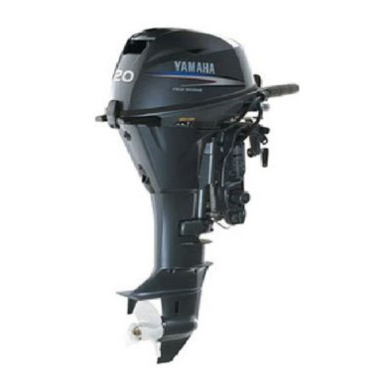
Yamaha F20A Owner's Manual
Hide thumbs
Also See for F20A:
- Service manual (445 pages) ,
- Owner's manual (232 pages) ,
- Owner's manual (86 pages)
Table of Contents
Advertisement
Quick Links
Advertisement
Table of Contents

Related Manuals for Yamaha F20A


Summary of Contents for Yamaha F20A
- Page 1 F20A F25A FT25B OWNER’S MANUAL 65W-28199-7B-E0...
- Page 2 EMU25050 Read this owner’s manual carefully before operating your outboard motor.
- Page 3 Yamaha. If you have any question about the also be voided. operation or maintenance of your outboard Some countries have laws or regulations re- motor, please consult a Yamaha dealer.
- Page 4 Important manual information EMU25120 F20A, F25A, FT25B OWNER’S MANUAL ©2005 by Yamaha Motor Co., Ltd. 1st Edition, February 2005 All rights reserved. Any reprinting or unauthorized use without the written permission of Yamaha Motor Co., Ltd. is expressly prohibited. Printed in Japan...
-
Page 5: Table Of Contents
Table of contents General information ......1 Trim tab with anode......15 Trim tab ........... 15 Identification numbers record..1 Trim rod (tilt pin) ......16 Outboard motor serial number ..1 Tilt lock mechanism......16 Key number........1 Tilt support knob......16 EC label........... - Page 6 Table of contents Tilting up and down ....... 33 Checking propeller ......56 Procedure for tilting up (manual Removing the propeller ....57 tilt models) ........33 Installing the Propeller..... 57 Procedure for tilting up ....34 Changing gear oil ......58 Procedure for tilting down Cleaning fuel tank ......
-
Page 7: General Information
Record your outboard motor serial number in the spaces provided to assist you in ordering spare parts from your Yamaha dealer or for reference in case your outboard motor is sto- len. 1. Key number... -
Page 8: Emission Control Information
Incorrect propeller selection and incorrect use may not only cause engine damage, but also adversely affect fuel consumption. Consult your dealer for correct use. YAMAHA MOTOR CO.,LTD. Never operate after drinking alcohol or tak- ing drugs. About 50% of all boating fatali- Motorfamilie ties involve intoxication. -
Page 9: Important Labels
Avoid blocking exhaust outlets. Never illegally discard (dump) the product. Check throttle, shift, and steering for prop- Yamaha recommends consulting the deal- er operation before starting the engine. er on discarding the product. Attach the engine stop switch lanyard to a... -
Page 10: Caution Labels
General information while engine is running. line spills, wipe it up immediately with dry rags. EMU25431 Do not overfill the fuel tank. Label Tighten the filler cap securely after re- EWM01300 WARNING fueling. This engine is equipped with a neutral If you should swallow some gasoline, starting device. -
Page 11: Engine Oil
General information EMU25683 Engine oil Recommended engine oil: 4-stroke motor oil with a combination of the following SAE and API oil classi- fications Engine oil type SAE: 10W-30 or 10W-40 Engine oil grade API: SE, SF, SG, SH, SJ, SL Engine oil quantity (excluding oil filter): F20AE 1.7 L (1.80 US qt) (1.50 Imp.qt) F20AET 1.7 L (1.80 US qt) (1.50... -
Page 12: Battery Specifications
Minimum cold cranking amps (CCA/EN): on the engine. F20AE 347.0 A Yamaha outboard motors are fitted with pro- F20AET 347.0 A pellers chosen to perform well over a range F25AE 347.0 A of applications, but there may be uses where F25AET 347.0 A... -
Page 13: Start-In-Gear Protection
For instructions on propeller removal and in- stallation, see page 56. EMU25760 Start-in-gear protection Yamaha outboard motors affixed with the pictured label or Yamaha-approved remote control units are equipped with start-in-gear protection device(s). This feature permits the engine to be started only when it is in neutral. -
Page 14: Basic Components
Basic components EMU25796 Main components NOTE: * May not be exactly as shown; also may not be included as standard equipment on all mod- els. F20A, F25A, FT25B 15 16 ZMU04968 1. Top cowling 15. Engine stop button/Engine stop lanyard switch* 2. -
Page 15: Fuel Tank
Basic components fuel tank, its function is as follows. EMU25830 Fuel joint EWM00020 This joint is used to connect the fuel line. WARNING EMU25841 The fuel tank supplied with this engine is Fuel gauge its dedicated fuel reservoir and must not This gauge is located on either the fuel tank be used as a fuel storage container. -
Page 16: Remote Control Lever
Basic components 6. Throttle 7. Fully open EMU26201 Neutral interlock trigger To shift out of neutral, first pull the neutral in- terlock trigger up. ZMU04862 1. Remote control lever 2. Neutral interlock trigger 3. Neutral throttle lever 4. Main switch / choke switch 5. -
Page 17: Tiller Handle
Basic components ZMU02285 1. Fully open 1. Forward “ ” 2. Fully closed 2. Neutral “ ” 3. Reverse “ ” EMU25911 Tiller handle EMU25941 To change direction, move the tiller handle to Throttle grip the left or right as necessary. The throttle grip is on the tiller handle. -
Page 18: Throttle Friction Adjuster
Basic components START ZMU02001 ZMU02286 When constant speed is desired, tighten the 1. Throttle indicator adjuster to maintain the desired throttle set- EMU25970 ting. Throttle friction adjuster EMU25990 A friction device provides adjustable resis- Engine stop lanyard switch tance to movement of the throttle grip or the The lock plate must be attached to the en- remote control lever, and can be set accord- gine stop switch for the engine to run. -
Page 19: Engine Stop Button
Basic components NOTE: The engine cannot be started with the lock plate removed. ZMU02083 EMU26070 Manual starter handle To start the engine, first gently pull the han- dle out until resistance is felt. From that posi- 1. Lanyard tion, then pull the handle straight out quickly 2. -
Page 20: Steering Friction Adjuster
Basic components gine. When the key is released, it returns EMU26141 Power trim and tilt switch on remote automatically to the “ ” (on) position. control or tiller handle The power trim and tilt system adjusts the outboard motor angle in relation to the tran- som. -
Page 21: Trim Tab With Anode
Basic components while the boat is moving could increase protect the engine from electrochemical the risk of falling overboard and could corrosion. Never paint the trim tab as it distract the operator, increasing the risk will become ineffective as an anode. of collision with another boat or an obsta- cle. -
Page 22: Trim Rod (Tilt Pin)
Basic components ZMU02291 ZMU02289 1. Tilt lock lever 1. Trim tab 2. Bolt To lock it, set the tilt lock lever in the lock po- sition. To release, push the tilt lock lever in EMU26261 Trim rod (tilt pin) the release position. The position of the trim rod determines the EMU26320 Tilt support knob... -
Page 23: Top Cowling Lock Lever(S) (Turn Type)
Do not continue to operate the engine if a ter passages of the motor using a garden warning device has activated. Consult hose and tap water. your Yamaha dealer if the problem can- NOTE: not be located and corrected. For details on usage, see page 44. -
Page 24: Low Oil Pressure Warning
Check the oil level and add oil as needed. If the oil level is correct and the warning device does not switch off, consult your Yamaha dealer. ECM00100 CAUTION: Do not continue to run the engine if the EMU30164 low oil pressure warning indicator is on. -
Page 25: Operation
Operation EMU26901 specific boat and motor combination. Installation EWM00830 ECM00110 WARNING CAUTION: Improper mounting of the outboard mo- Incorrect engine height or obstructions tor could result in hazardous conditions to smooth water flow (such as the design such as poor handling, loss of control, or or condition of the boat, or accessories fire hazards. -
Page 26: Clamping The Outboard Motor
Other- termine the optimum mounting height. wise the engine could be completely lost Consult your Yamaha dealer or boat man- if it accidentally falls off the transom. ufacturer for further information on deter- mining the proper mounting height. -
Page 27: Breaking In Engine
Check fuel line connections to be sure they ECM00800 CAUTION: are tight (if equipped Yamaha fuel tank or Failure to follow the break-in procedure boat tank). could result in reduced engine life or Be sure the fuel tank is positioned on a se- even severe engine damage. -
Page 28: Engine
Operation er operation before starting the engine. The controls should work smoothly, with- out binding or unusual free play. Look for loose or damaged connections. Check operation of the starter and stop switches when the outboard motor is in the water. -
Page 29: Operating Engine
Operation Wipe up any spilled fuel. Fuel tank capacity: 24 L (6.34 US gal) (5.28 Imp.gal), 25 L (6.60 US gal) (5.50 Imp.gal) NOTE: The smaller fuel filling hole on the fuel tank has been designed to fit unleaded fuel fillers only for emission control models (for Bod- ZMU02295 ensee). -
Page 30: Starting Engine
Operation from the fuel tank. to a secure place on your clothing, or your arm or leg while operating. Squeeze the primer pump with the outlet Do not attach the lanyard to clothing end up until you feel it become firm. that could tear loose. - Page 31 Operation arm or leg. Then install the lock plate on the other end of the lanyard into the en- gine stop switch. EWM00120 WARNING Attach the engine stop switch lanyard to a secure place on your clothing, or your arm or leg while operating. Do not attach the lanyard to clothing ZMU02336 that could tear loose.
-
Page 32: Warming Up Engine
Do not keep the starter motor turning level and add oil if necessary. Consult for more than 5 seconds. If the starter your Yamaha dealer if the cause for the motor is turned continuously for more low oil pressure warning indicator can- than 5 seconds, the battery will be not be found. -
Page 33: Shifting
Operation firmly from neutral to forward. ZMU02034 ZMU02298 EMU27740 Shifting Remote control models EWM00180 Pull up the neutral interlock trigger (if WARNING equipped) and move the remote control Before shifting, make sure there are no lever quickly and firmly from neutral to swimmers or obstacles in the water near forward. -
Page 34: Reverse (Manual Tilt And Hydro Tilt Models)
Operation EMU27795 Reverse (manual tilt and hydro tilt models) EWM00190 WARNING START When operating in reverse, go slowly. Do not open the throttle more than half. Oth- erwise the boat could become unstable, which could result in loss of control and ZMU02297 an accident. -
Page 35: Stopping Engine
Operation ping the engine immediately after operating at high speed is not recommended. EMU27844 Procedure Push and hold the engine stop button or turn the main switch to “ ” (off). ZMU02300 Remote control models Check that the tilt lock lever is in the lock position. -
Page 36: Trimming Outboard Motor
Operation ZMU02041 Remove the key if the boat will be left unattended. NOTE: The engine can also be stopped by pulling the lanyard and removing the lock plate from the engine stop switch, then turning the main switch to “ ”... -
Page 37: Adjusting Trim Angle
Operation EMU27881 Adjusting trim angle Power trim and tilt models EWM00750 WARNING Be sure all people are clear of the out- board motor when adjusting the tilt an- gle, also be careful not to pinch any body parts between the drive unit and ZMU02890 clamp bracket. -
Page 38: Adjusting Boat Trim
Operation ZMU02811 Bow Up To raise the bow (trim-out), press the switch Too much trim-out puts the bow of the boat “ ” (up). too high in the water. Performance and econ- To lower the bow (trim-in), press the switch omy are decreased because the hull of the “... -
Page 39: Tilting Up And Down
Operation on page 29. Never tilt the outboard mo- tor while the engine is running. Severe damage from overheating can result. Do not tilt up the engine by pushing the tiller handle (if equipped) because this could break the handle. EMU27976 Procedure for tilting up (manual tilt models) -
Page 40: Procedure For Tilting Up
Operation EMU28005 Procedure for tilting up Power trim and tilt models / power tilt models Place the remote control lever / the gear shift lever in neutral. ZMU02302 Place the tilt lock lever (if equipped) in the release/up position. Disconnect the fuel line from the out- board motor or close the fuel cock. -
Page 41: Procedure For Tilting Down (Manual Tilt Models)
Operation from marine growth and corrosion which could damage the power trim and tilt mechanism. EMU30190 Procedure for tilting down (manual tilt models) Place the tilt lock lever in the lock posi- tion. ZMU02823 Push the tilt support knob into the clamp bracket or pull the tilt support lever to- ward you to support the engine. -
Page 42: Cruising In Shallow Water
Operation Push the power tilt / power trim and tilt the water, resulting in loss of control. switch “ ” (down) to lower the outboard Do not rotate the outboard motor 180° motor to the desired position. and operate the boat in reverse. Place the gear shift in reverse to operate the boat in reverse. -
Page 43: Power Trim And Tilt Models / Power Tilt Models
Operation ZMU02304 ZMU02306 Place the tilt lock lever in the release/up Slightly tilt the outboard motor up until position. the tilt support bar automatically returns to the free position. Slowly lower the outboard motor to the normal position. EMU28090 Power trim and tilt models / power tilt models The outboard motor can be tilted up partially to allow operation in shallow water. -
Page 44: Cruising In Other Conditions
For cooling system flushing instructions, see page 41. Cruising in turbid water Yamaha strongly recommends that you use the optional chromium-plated water pump kit (not available for some models) if you use Slightly tilt the outboard motor up to the... -
Page 45: Maintenance
Maintenance EMU28217 Weight (AL) L: Specifications F20AET 67.0 kg (148 lb) Dimension: F25AE 67.0 kg (148 lb) Overall length: F25AET 71.0 kg (157 lb) F20AE 703 mm (27.7 in) F25AMH 64.0 kg (141 lb) F20AET 703 mm (27.7 in) FT25BET 86.7 kg (191 lb) F25AE 703 mm (27.7 in) Performance: F25AET 703 mm (27.7 in) - Page 46 Maintenance Spark plug (NGK): F25AE 15.0 A DPR6EA-9 F25AET 15.0 A Spark plug gap: FT25BET 15.0 A 0.8–0.9 mm (0.031–0.035 in) Drive unit: Control system: Gear positions: F20AE Remote control Forward-neutral-reverse F20AET Remote control Gear ratio: F25AE Remote control F20AE 2.08 (27/13) F25AET Remote control F20AET 2.08 (27/13) F25AMH Tiller...
-
Page 47: Transporting And Storing Outboard Motor
Maintenance 4-stroke outboard motor oil F20AET 35.0 Nm (25.8 ft-lb) (3.57 Engine oil grade API: kgf-m) API SE, SF, SG, SH, SJ, SL F25AE 35.0 Nm (25.8 ft-lb) (3.57 Engine oil type SAE: kgf-m) SAE10W30 or SAE10W40 F25AET 35.0 Nm (25.8 ft-lb) (3.57 Lubrication: kgf-m) Wet sump... -
Page 48: Clamp Screw Mounting Models
Yamaha dealer sition using a motor support device such as prior to storage. However, you, the owner, a transom saver bar. Consult your Yamaha with a minimum of tools, can perform the fol- dealer for further details. -
Page 49: Procedure
Maintenance ventilated place, not in direct sunlight. of the anti-cavitation plate, or if the water supply is insufficient, engine seizure may EMU28301 occur. Procedure EMU28332 Cooling system flushing is essential to Flushing in a test tank prevent the cooling system from clog- ECM00300 ging up with salt, sand, or dirt. -
Page 50: Lubrication (Except Oil Injection Models)
FLUID OUT OF REACH OF CHILDREN. ence of water that indicates a leaky seal. Batteries vary among manufacturers. There- Seal replacement should be performed by an authorized Yamaha dealer prior to fore the following procedures may not al- ways apply. -
Page 51: Cleaning The Outboard Motor
Maintenance overheating can result. tor securely. ECM00540 After shutting off the engine, unscrew CAUTION: the garden hose connector from the fit- Do not leave the garden hose connector ting on the bottom cowling. loose on the bottom cowling fitting or let the hose hang free during normal opera- tion. -
Page 52: Periodic Maintenance
Be sure to turn off the engine when you perform maintenance unless otherwise specified. If you or the owner is not famil- iar with machine servicing, this work should be done by your Yamaha dealer or other qualified mechanic. EMU28510 Replacement parts... -
Page 53: Maintenance Chart
When operating in salt water, turbid or muddy water, the engine should be flushed with clean water after each use. The “ ” symbol indicates the check-ups which you may carry out yourself. The “ ” symbol indicates work to be carried out by your Yamaha dealer. Initial Every 50 hours Item... -
Page 54: Maintenance Chart (Additional)
Maintenance Initial Every 50 hours Item Actions 10 hours hours (6 hours (1 (1 month) months) months) year) Inspection / replace- Water pump ment Engine oil Inspection / change Oil filter (cartridge) Change Cleaning / adjustment / Spark plug(s) replacement Inspection / replace- Timing belt ment... -
Page 55: Greasing
Maintenance EMU28940 Greasing Yamaha grease A (water resistant grease) Yamaha grease D (corrosion resistant grease; for propeller shaft) F25AMH ZMU02307... -
Page 56: Cleaning And Adjusting Spark Plug
Maintenance F20AE, F20AET, F25AE, F25AET, FT25BET ZMU02827 EMU28952 Yamaha dealer. You should periodically re- Cleaning and adjusting spark plug move and inspect the spark plug because EWM00560 heat and deposits will cause the spark plug WARNING to slowly break down and erode. If electrode... -
Page 57: Checking Fuel System
1. Spark plug gap Check the fuel lines for leaks, crack, or mal- 2. Spark plug I.D. mark (NGK) function. If a problem is found, your Yamaha dealer or other qualified mechanic should re- Spark plug gap: pair it immediately. -
Page 58: Inspecting Fuel Filter
If any water is found in the If you have any question about properly fuel, the Yamaha portable fuel tank or doing this procedure, consult your other fuel tanks should be checked and Yamaha dealer. -
Page 59: Changing Engine Oil
If you have difficulty ver- ifying the idle speed, or the idle speed re- quires adjustment, consult a Yamaha dealer or other qualified mechanic. Verify whether the idle speed is set to specification. - Page 60 Con- torque wrench as soon as possible. tinued operation with a problem could Add the correct amount of oil through the cause severe engine damage. Consult your Yamaha dealer if the problem can-...
-
Page 61: Checking Wiring And Connectors
Check for oil leaks on the around the engine. For more information on the disposal of NOTE: used oil, consult your Yamaha dealer. If any leaks are found, consult your Yamaha Change the oil more often when operating dealer. the engine under adverse conditions such as extended trolling. -
Page 62: Checking Propeller
Tilt the outboard motor down. Check that the trim and tilt rod / the tilt rod oper- ates smoothly. NOTE: Consult your Yamaha dealer if any operation is abnormal. ZMU01897 EMU29171 Checking propeller... -
Page 63: Removing The Propeller
Be sure to use a new cotter pin and bend the ends over securely. Otherwise the propeller could come off during op- eration and be lost. Apply Yamaha marine grease or a cor- rosion resistant grease to the propeller shaft. 1. Cotter pin 2. -
Page 64: Changing Gear Oil
NOTE: stand. You could be severely injured if For disposal of used oil consult your Yamaha the outboard motor falls on you. dealer. Never get under the lower unit while it... -
Page 65: Cleaning Fuel Tank
Maintenance the gear oil drain screw hole. Yamaha dealer. Keep away from sparks, cigarettes, Recommended gear oil: flames, or other sources of ignition Hypoid gear oil SAE#90 when cleaning the fuel tank. Gear oil quantity: Remove the fuel tank from the boat be- F20AE 320.0 cm... -
Page 66: Inspecting And Replacing Anode(S)
EMU29312 Inspecting and replacing anode(s) Yamaha outboard motors are protected from ZMU02820 corrosion by sacrificial anodes. Inspect the external anodes periodically. Remove scales from the surfaces of the anodes. Consult a Yamaha dealer for replacement of external anodes. -
Page 67: Connecting The Battery
NOTE: DO NOT SMOKE when charging or han- Consult a Yamaha dealer when charging or dling batteries. re-charging batteries. KEEP BATTERIES AND ELECTROLYTIC EMU29331 FLUID OUT OF REACH OF CHILDREN. -
Page 68: Disconnecting The Battery
ATIVE (-) terminal first. Then disconnect the ZMU01943 RED cable from the POSITIVE (+) terminal. EMU29390 Checking top cowling Check the fitting of the top cowling by push- ing it with both hands. If it is loose have it re- paired by your Yamaha dealer. -
Page 69: Trouble Recovery
Q. Has fuel pump malfunctioned? If your outboard motor requires repair, bring A. Have serviced by a Yamaha dealer. it to your Yamaha dealer. If the engine trouble warning indicator is Q. Are spark plug(s) fouled or of incorrect flashing, consult your Yamaha dealer. - Page 70 Q. Is fuel contaminated or stale? A. Fill tank with clean, fresh fuel. Q. Is carburetor clogged? A. Have serviced by a Yamaha dealer. Q. Is fuel filter clogged? A. Clean or replace filter. Q. Is fuel joint connection incorrect? A.
- Page 71 Trouble Recovery A. Have serviced by a Yamaha dealer. Q. Are weeds or other foreign matter tangled on gear housing? Q. Is load on boat improperly distributed? A. Remove foreign matter and clean lower A. Distribute load to place boat on an even unit.
-
Page 72: Temporary Action In Emergency
EWM00630 Q. Is steering pivot loose or damaged? WARNING A. Tighten or have serviced by a Yamaha Be sure to use the specified fuse. An in- dealer. correct fuse or a piece of wire could allow EMU29432 excessive current flow. -
Page 73: Power Trim And Tilt / Power Tilt Will Not Operate
Make sure the remote control lever NOTE: is in neutral. Otherwise the boat could Consult your Yamaha dealer if the new fuse unexpectedly start to move, which immediately blows again. could result in an accident. -
Page 74: Emergency Starting Engine
Trouble Recovery engine is running. Do not install the starter mechanism or top cowling after the engine is running. Do not touch the ignition coil, spark plug wire, spark plug cap, or other elec- trical components when starting or op- erating the motor. -
Page 75: Treatment Of Submerged Motor
ECM00400 CAUTION: If the outboard motor is submerged, immedi- Do not attempt to run the outboard motor ately take it to a Yamaha dealer. Otherwise until it has been completely inspected. some corrosion may begin almost immedi- ately. If you cannot immediately take the outboard... - Page 76 YAMAHA MOTOR CO., LTD. Printed in Japan April 2005–0.5 × 1 ! Printed on recycled paper...
Need help?
Do you have a question about the F20A and is the answer not in the manual?
Questions and answers