Table of Contents
Advertisement
Quick Links
1
注:此页为技术说明,非印刷内容
A
刀模线:
内折线:
展开尺寸图:
B
C
装订效果图:
D
技术要求:
1、材质:封页105g 铜板纸;内页80g双胶纸
2、展开尺寸:A4,如图所示装订成型为A5,44P
E
3、颜色:单色
4、印刷:印刷图档见后续页,双面印刷
5、装订方式:骑马钉
##
.XXX
0-30
±1
30-150
±2
##
150-300
±3
(.XXX)
300-450
±4
>450
±5
1
2
297mm
封
底
Lia
2023/06/01
2
3
封
面
ERDHM2-01B-
Manual(英法西)-XX
3
4
210mm
XXX-XXXXX-XX
00
1
1
深圳市倍思奇创
新科技有限公司
4
A
B
C
D
E
F
Advertisement
Table of Contents

Subscribe to Our Youtube Channel
Related Manuals for ErgoAV ERDHM2-01B


Summary of Contents for ErgoAV ERDHM2-01B
- Page 1 注:此页为技术说明,非印刷内容 刀模线: 内折线: 展开尺寸图: 297mm 210mm 装订效果图: 封 封 底 面 技术要求: 1、材质:封页105g 铜板纸;内页80g双胶纸 2、展开尺寸:A4,如图所示装订成型为A5,44P 3、颜色:单色 4、印刷:印刷图档见后续页,双面印刷 5、装订方式:骑马钉 XXX-XXXXX-XX ERDHM2-01B- Manual(英法西)-XX .XXX 0-30 ±1 30-150 ±2 2023/06/01 150-300 ±3 深圳市倍思奇创 (.XXX) 300-450 ±4 新科技有限公司 >450 ±5...
- Page 2 Model: ERDHM2-01B Thank You for Choosing this ErgoAV Product! At ErgoAV, we want to add value to your AV experience by providing the highest quality products and services in the industry. If you have any concerns or comments, please contact us.
-
Page 3: Important Safety Information
• This product contains gas assist arms which are under pressure. Do not puncture these arms or expose the arms to high heat. • If the product arrives defective or is missing parts, please contact ErgoAV Customer Support at support@ergoav.com or (877) 419-7832 to arrange a return. -
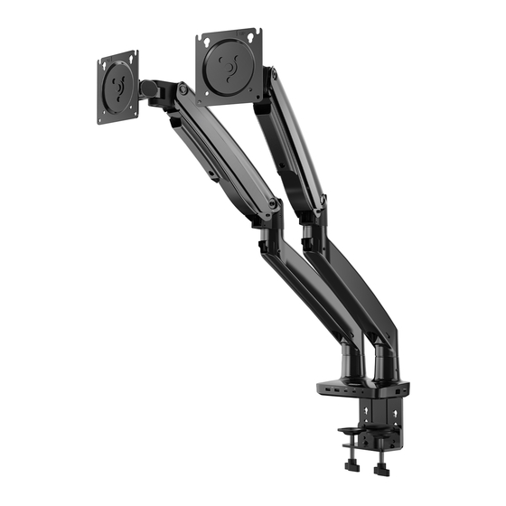
Page 4: Product Features
Product Features 360° 360° 180° +45° 15.2” (385mm) 7.3” (185mm) C-Clamp Mounting for table edge 0.79” ~ 3.54” (20–90mm) Grommet Mounting for grommet bolt 0.79 ~ 3.54 ” ” (20~90mm) - Page 5 TENSION ADJUSTMENT SHOULD BE DONE ONLY AFTER MOUNT INSTALLATION Attention DO NOT adjust tension without monitor attached. 1. Verify the weight of your monitor (including accessories) is between 4.4 ~ 22 Ibs (2.0~10.0 kg). 2. Monitor weight information can be found within its box or manual. 3.
-
Page 6: Supplied Parts And Hardware
Before starting assembly, verify all parts are included and undamaged. Do not use damaged or defective parts. lf you require replacement parts, please contact Technical Support at (877) 419-7832 or Customer Service at support@ergoav.com to find a compatible mount. • NOTE: Not all hardware included in this package will be used. - Page 7 1A-2 Attach the C-clamp brace to the 1A-3 Install the Rubber Pad [C] on the Base [01] using Bolts [B1]. Base [01]. WARNING: Ensure bolts are secured firmly. 1A-4 After pushing the clamp fully onto the desk, rotate the knob until the C-Clamp [02] is secured firmly to the underside of desktop.
- Page 8 Option B: Existing Grommet Hole Installation ATTENTION: Ensure the grommet bolt is threaded securely to the base. NOTE: If your desk has an existing grommet hole with a plastic cover, remove it before installation. 3/4" ~ 3 1/2" 0.79”–3.54” 20~90mm 20~90mm Rotate Butterfly Nut [A3] until the Locking Plate [A1] is firmly secured to the underside of your desk.
- Page 9 Option C: Self Drilled Grommet Hole Installation ATTENTION: Ensure the grommet bolt is threaded securely to the base. If a hole is needed for grommet installation, be sure to leave at least 2” from the edge of desktop and mark where the hole will be drilled. Use either a 7/16” or 7/8” drill bit for this step.
- Page 10 Supplied Parts and Hardware for Step 2 Arm Extender Small Allen Key 1/8” (3mm) [L3] x 1 Step 2 Attach the Arm Sections 2-1 Push the Arm Extender [03] into the base, and then the Arm [04] onto the Arm Extender [03].
- Page 11 Step 3 Attach the Monitor Plate Slide the Monitor Plate [05] sideways into the slot at the end of the Arm [04]. Fasten with Bolt [D1] and Washer [D2]. Supplied Parts and Hardware for Step 4 Washer Bolt Bolt Spacer Large Allen Key 10 x 4.5 x 1.0mm M4 x 12mm...
- Page 12 Bolt length: Verify adequate thread engagement with bolts or bolts / spacers combination. We recommend thread engagement of at least 5 turns. -Too short will NOT hold the monitor. -Too long will damage the monitor. Too Short Too Long Correct Correct Option A (For Flat Back Monitor) 4A-1 Thread two Bolts [F1] with Washers [E1] into the top holes until about 0.1–0.2"...
- Page 13 Option B (For Curved Back Monitor) 4B-1 Slide the Washers [E1] and Spacers [H1] over the Bolts [G1]. Turn the top two Bolts [G1] CLOCKWISE until about 0.1–0.2" (3–5mm) of space is left between the Washer [E1] and the Spacer [H1]. E1 H1 0.1–0.2"...
- Page 14 Supplied Hardware for Step 5 Large Allen Key 3/16” (5mm) [L2] x 1 Step 5 Adjust the Gas Spring Tension 5-1 If the gas spring arm RISES with the monitor attached, hold the arm in a horizontal position while using the large Allen Key [L2] to turn the adjustment bolt CLOCKWISE, REDUCING the arm tension.
- Page 15 Step 6 Rotation Restriction To ensure proper stability, do not position monitor behind base. Monitor and arms should remain over the desktop. Failure to do so may cause instability, resulting in property damage or injury. Incorrect orientation Correct orientation Supplied Hardware for Step 7 Large Allen Key 3/16”...
-
Page 16: Step 9 Rotation Adjustment
Supplied Hardware for Step 8 and Step 10 Small Allen Key Large Allen Key 1/8” (3mm) 3/16” (5mm) [L3] x 1 [L2] x 1 Step 8 Swivel Adjustment 360° 360° 180° 180° WARNING: Do not overtighten or overloosen the bolts. Turn adjustment set screw CLOCKWISE to INCREASE the swiveling tension. - Page 17 Step 10 Route Cables along the Arm ③ ② ④ ① ⑤ ⑤ ① ③ ② ④...
- Page 18 • After connecting your USB C cable to the Hubs corresponding port, your computer will automatically detect the file ErgoAV by displaying an external drive on your desktop. • 3.5 mm AUX output. Connect earphones or other audio devices.
- Page 19 System Requirements for Monitor Mounts with Dock 4k@60Hz Operating System(Port 8): • Win10, Win11 or later • Mac OS 10.12~13.3.1 versions (support M1 & M2 & Intel chip) or later • Chrome OS 48.0.2564.82 or later • iPad OS 12 or later •...
- Page 20 At ErgoAV, we strive to provide the highest value products. We want to support your purchase. If you have questions, concerns, or feedback please let us know! ErgoAV Customer Care Phone (877) 419-7832 support@ergoav.com Electric Standing Desk TV Mount Tabletop TV Stands 9501 Louisiana Ave N, #200, Brooklyn Park, MN 55445 www.ergoav.com...
Need help?
Do you have a question about the ERDHM2-01B and is the answer not in the manual?
Questions and answers