Advertisement
Quick Links
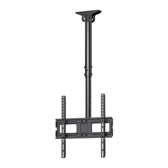
Ceiling TV Mount Instruction Manual
(A)
Model: ERMCM1-01B
Thank You for Choosing this ErgoAV Product!
At ErgoAV, we want to add value to your AV experience by providing the
highest quality products and services in the industry. If you have any
concerns or comments, please contact us.
ErgoAV Customer Care
Phone: (877) 419-7832
Email: support@ergoav.com
Website: www.ergoav.com
Address: 9501 Louisiana Ave N, #200, Brooklyn Park, MN 55445
Advertisement

Related Manuals for ErgoAV ERMCM1-01B


Summary of Contents for ErgoAV ERMCM1-01B
- Page 1 Model: ERMCM1-01B Thank You for Choosing this ErgoAV Product! At ErgoAV, we want to add value to your AV experience by providing the highest quality products and services in the industry. If you have any concerns or comments, please contact us.
-
Page 2: Weight Restrictions
DANGER! Please carefully read all instructions before attempting installation. If you do not understand the instructions or have any concerns, please contact our Technical Support at (877) 419-7832 or Customer Service at support@ergoav.com. CAUTION: Avoid potential personal injuries and property damage! •... -
Page 3: Supplied Parts And Hardware
Before starting assembly, verify all parts are included and undamaged. Do not use damaged or defective parts. If you require replacement parts, please contact our Technical Support at (877) 419-7832 or Customer Service at support@ergoav.com. • PLEASE NOTE: Not all hardware included in this package will be used. - Page 4 NOTE: The bolts shown are in actual size. TV Bolts (Only one size of the bolt fits your TV) M4x12mm M4x30mm [C1] x4 [C2] x4 M6x15mm M6x35mm [D1] x4 [D2] x4 M8x25mm M8x50mm [E1] x4 [E2] x4 Step 1 Secure the TV Brackets to the TV Select TV Bolts Only one size of the bolt fits your TV.
- Page 5 If you have any difficulty understanding how to install the TV Bolts or Spacers, please contact our Technical Support at (877) 419-7832 or Customer Service at support@ergoav.com. Parts Needed if You Have a TV as Shown Below Curved TV See...
- Page 6 Option A (For Flat Back C1/D1/E1 B1/B2 (If needed) Refer back to Spacer Instructions on Page 5, If needed Phillips Screwdriver (Not lncluded) Option B (For Curved Back TV) Spacers must be tall enough so that the curve on the back of the TV will not interfere with the mounting plate.
- Page 7 Option C (For TV with A “Bump”) Spacers must be tall enough so there is no gap between TV bracket and bump on the back of the TV. C2/D2/E2 B1/B2 F1/F2/F3 Refer back to Spacer Instructions on Page 5, If needed Phillips Screwdriver (Not lncluded) Option D (for TV with Cable Interference)
- Page 8 Option E (For Recessed Holes ) The Spacers need to fill in the recessed holes on the back of the TV so that the TV Brackets are as close to the TV as possible. C2/D1/ B1/B2 F1/F2/F3 Phillips Screwdriver (Not lncluded) Refer back to Spacer Instructions on Page 5, If needed Supplied Parts and Hardware for Step 2...
- Page 9 Step 2 Attach the Ceiling Plate to the Top of the Upper Pole 3/8” (10mm) 3/16” (5mm) Socket Wrench Allen Key (NOT Included) [05] Supplied Hardware for Step 3 NOTE: The lag screw is shown in actual size. Lag Screw 5/16”...
- Page 10 Step 3 Secure the Ceiling Plate to the Ceiling For wood stud installation, follow STEP 3A For concrete installation, follow STEP 3B Step 3A Wood Stud Option WARNING: ● To avoid personal injury or property damage, Do Not over-tighten the Lag Screws [A1].
- Page 11 3A-3 2 3/4" (70mm) Electric Drill 7/32" (5.5mm) (NOT Included) CAUTION: DO NOT drill the holes at the edge of the ceiling joist. Make sure the holes are drilled on the center location of the ceiling joist. Drill 4 pilot holes using a 7/32" (5.5mm) diameter drill bit.
- Page 12 3B-1 Ceiling Thickness ≥5 1/2" (140mm) Pencil (NOT Included) Position the Ceiling Plate [02] at your desired position, and mark the pilot hole locations. 3B-2 3” (75mm) Electric Drill 3/8” (10mm) (NOT Included) Drill the 4 pilot holes using a 3/8”...
- Page 13 Supplied Parts and Hardware for Step 4 Bolt M6x60mm TV Plate M6 Washer 3/16 in(5mm) M6 Nut Allen Key Lower Pole Step 4 Secure Poles with TV Plate to the Lower Pole 4-1 Slide the TV Plate [07] onto the Lower Pole [09]. Keep arrow up...
- Page 14 Align the holes in the Lower Pole [09] with the holes in the Upper Pole [01]. Height adjustments can be made by selecting different holes in Lower Pole [09]. Using Bolts [b4], Washers [b3], and Nuts [b5], attach the poles together at desired height.
- Page 15 Step 5-2 Hang the TV on the TV Plate. Step 5-3 Tighten the Bolts [K] on the safety locks into place Phillips Screwdriver until they are pulled firmly against the TV Plate. (NOT lncluded) HEAVY! You may need assistance with this step. Step 5-2 Step 5-3 Locking...
- Page 16 Swivel Adjustment for TV Level Adjustment for TV Loosen Tighten 1. Slightly loosen the four pre-assembled Bolts [b7] with the Wrench [10]. 2. Adjust the TV to your desired position. 3. Tighten the Bolts [b7] to secure the tilt angle into place.
- Page 17 Tilt Adjustment for TV 1. Slightly loosen the two upper pre-assembled bolts [T] with a Wrench [10]. 2. Adjust the TV to your desired position. Loosen Loosen 3. Tighten the Bolt [T] to secure the tilt angle into place. Tighten Step 7 Route the Cables along with the Pole NOTE: To prevent excess stress on connectors and cables, leave...
- Page 20 At ErgoAV, we strive to provide the highest value products. We want to support your purchase. If you have questions,concerns, or feedback please let us know! ErgoAV Customer Care Phone (877) 419-7832 support@ergoav.com Speaker Stands Computer Monitor Mounts Tabletop TV Stand 9501 Louisiana Ave N, #200, Brooklyn Park, MN 55445 WWW.ERGOAV.COM...
Need help?
Do you have a question about the ERMCM1-01B and is the answer not in the manual?
Questions and answers