Table of Contents
Advertisement
Quick Links
SERVICE MANUAL
Ver 1.1 2002. 03
Sony Corporation
9-873-557-02
2002C0400-1
e Vehicle Company
© 2002. 03
Published by Sony Engineering Corporation
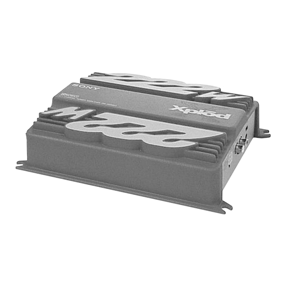
XM-222MK2
SPECIFICATIONS
Circuit system
OTL (output transformerless) circuit Pulse
power supply
Inputs
RCA pin jacks
High level input connector
Input level adjustment range
0.3 – 6 V (RCA pin jacks),
0.6 – 12 V (High level input)
Outputs
Speaker terminals
Speaker impedance
2 – 8 Ω (stereo)
4 – 8 Ω (when used as a bridging amplifier)
Maximum outputs
100 W × 2 (at 4 Ω)
222 W (BTL, at 4 Ω)
Rated outputs (supply voltage at 14.4 V)
35 W × 2 (20 Hz – 20 kHz, 0.04% THD, at 4 Ω)
40 W × 2 (20 Hz – 20 kHz, 0.1% THD, at 2 Ω)
80 W (Monaural) (20 Hz – 20 kHz, 0.1% THD,
at 4 Ω)
+0
Frequency response
5 Hz – 80 kHz (
–3
Harmonic distortion
0.005% or less (at 1 kHz, 4 Ω, 10 W)
Low-pass filter
80 Hz, –18 dB/oct
Power requirements
12 V DC car battery
(negative ground)
Power supply voltage
10.5 – 16 V
Current drain
at rated output : 12 A (4 Ω, 35 W × 2)
Remote input : 1.5 mA
Dimensions
Approx. 205 × 55 × 158 mm (w/h/d) not incl.
projecting parts and controls
Mass
Approx. 1.6 kg not incl. accessories
Supplied accessories
Mounting screws (4)
High level input cord (1)
Protection cap (1)
Design and specifications are subject to change without
notice.
dB)
STEREO POWER AMPLIFIER
Canadian Model
AEP Model
UK Model
E Model
1
Advertisement
Table of Contents

Summary of Contents for Sony Xplod XM-222MK2
- Page 1 Supplied accessories Mounting screws (4) High level input cord (1) Protection cap (1) Design and specifications are subject to change without notice. STEREO POWER AMPLIFIER Sony Corporation 9-873-557-02 2002C0400-1 e Vehicle Company © 2002. 03 Published by Sony Engineering Corporation...
-
Page 2: Table Of Contents
LES COMPOSANTS IDENTIFIÉS PAR UNE MARQUE 0 SUR LES DIAGRAMMES SCHÉMATIQUES ET LA LISTE DES PIÈCES SONT CRITIQUES POUR LA SÉCURITÉ DE FONCTIONNEMENT. NE REMPLACER CES COMPOSANTS QUE PAR DES PIÈCES SONY DONT LES NUMÉROS SONT DONNÉS DANS CE MANUEL OU DANS LES SUPPLÉMENTS PUBLIÉS PAR SONY. - Page 3 XM-222MK2 SECTION 1 GENERAL This section is extracted from instruction manual.
- Page 4 XM-222MK2...
-
Page 5: Disassembly
XM-222MK2 SECTION 2 DISASSEMBLY Note : This set can be disassemble according to the following sequence. 2-1. BOTTOM PLATE (Page 5) 2-2. HEAT SINK (Page 6) 2-3. AMP BOARD (Page 6) Note : Follow the disassembly procedure in the numerical order given. 2-1. -
Page 6: Heat Sink
XM-222MK2 2-2. HEAT SINK 1 BVTP 3x8 2 BVTP 3x8 3 AMP board 4 heat sink 2-3. AMP BOARD 2 rear panel 1 BVTP 3x8 4 front panel 5 AMP board 3 BVTP 3x8... -
Page 7: Diagrams
XM-222MK2 SECTION 3 DIAGRAMS 3-1. BLOCK DIAGRAM PRE AMP IC801 (1/2) GAIN CONTROL IC802 (1/2) CN802 IC803 (1/2) L (BTL) SPEAKER DIFFERENTIAL SWITCH DRIVE AMP DRIVE AMP POWER AMP Q101 Q104 Q108 Q110 Q102 S801-1 (80Hz) VR801-1 BIAS LEVEL Q106,107 CNJ801 OVERLOAD INPUT... -
Page 8: Printed Wiring Board
XM-222MK2 3-2. PRINTED WIRING BOARD • Refer to page 10 for Semiconductor Location and Common Note on Printed Wiring Boards. AMP BOARD D952 D951 Q903 Q904 PL801 CN801 K A K A K A S D G S D G C805 JW11 JW12... -
Page 9: Schematic Diagram
XM-222MK2 3-3. SCHEMATIC DIAGRAM • Refer to page 10 for IC Block Diagram and Common Note on Schematic Diagrams. D101 R118 C856 R114 R116 Q108 Q104 C113 Q107 R124 R133 C119 R138 Q110 Q112 R126 R129 R137 C120 R139 R119 R122 C115 Q102... -
Page 10: Exploded View
XM-222MK2 Ver 1.1 SECTION 4 EXPLODED VIEW • Semiconductor NOTE: THIS NOTE IS COMMON FOR PRINTED WIRING Location • The mechanical parts with no reference • Color Indication of Appearance Parts The components identified by BOARDS AND SCHEMATIC DIAGRAMS. number in the exploded views are not supplied. Example : mark 0 or dotted line with mark. -
Page 11: Electrical Parts List
XM-222MK2 Ver 1.1 SECTION 5 ELECTRICAL PARTS LIST NOTE: • Due to standardization, replacements in • Items marked “*” are not stocked since The components identified by mark 0 or dotted line with mark the parts list may be different from the they are seldom required for routine service. - Page 12 XM-222MK2 Ver 1.1 Ref. No. Part No. Description Remark Ref. No. Part No. Description Remark < CONNECTOR > < COIL > * CNJ802 1-691-785-11 PIN, CONNECTOR (PC BOARD) 4P (HI LEVEL L901 1-428-975-11 COIL, CHOKE 157uH (INPUT)) L951 1-410-396-41 INDUCTOR, FERRITE BEAD 0.45uH <...
- Page 13 XM-222MK2 Ref. No. Part No. Description Remark Ref. No. Part No. Description Remark < RESISTOR > R214 1-216-234-00 RES-CHIP 1/8W R215 1-216-823-11 METAL CHIP 1.5K 1/16W R101 1-216-837-11 METAL CHIP 1/16W R216 1-216-823-11 METAL CHIP 1.5K 1/16W R102 1-216-837-11 METAL CHIP 1/16W R217 1-216-234-00 RES-CHIP...
- Page 14 XM-222MK2 Ver 1.1 Ref. No. Part No. Description Remark Ref. No. Part No. Description Remark R903 1-216-833-11 METAL CHIP 1/16W PARTS FOR INSTALLATION AND CONNECTIONS R904 1-216-190-00 RES-CHIP 1/8W *************************************** R905 1-216-829-11 METAL CHIP 4.7K 1/16W R906 1-216-190-00 RES-CHIP 1/8W 3-367-410-01 SCREW (DIA.5X15), TAPPING R907 1-216-190-00 RES-CHIP...
- Page 15 XM-222MK2 MEMO...
- Page 16 XM-222MK2 REVISION HISTORY Clicking the version allows you to jump to the revised page. Also, clicking the version at the upper right on the revised page allows you to jump to the next revised page. Ver. Date Description of Revision 2002.


Need help?
Do you have a question about the Xplod XM-222MK2 and is the answer not in the manual?
Questions and answers