Advertisement
SERVICE MANUAL
Ver 1.1 2002. 03
Sony Corporation
9-873-557-02
2002C0400-1
e Vehicle Company
© 2002. 03
Published by Sony Engineering Corporation
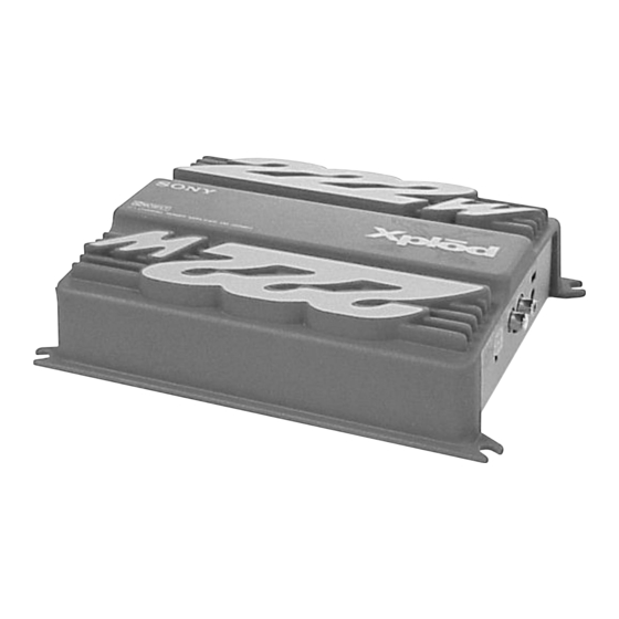
XM-222MK2
SPECIFICATIONS
Circuit system
OTL (output transformerless) circuit Pulse
power supply
Inputs
RCA pin jacks
High level input connector
Input level adjustment range
0.3 – 6 V (RCA pin jacks),
0.6 – 12 V (High level input)
Outputs
Speaker terminals
Speaker impedance
2 – 8 Ω (stereo)
4 – 8 Ω (when used as a bridging amplifier)
100 W × 2 (at 4 Ω)
Maximum outputs
222 W (BTL, at 4 Ω)
Rated outputs (supply voltage at 14.4 V)
35 W × 2 (20 Hz – 20 kHz, 0.04% THD, at 4 Ω)
40 W × 2 (20 Hz – 20 kHz, 0.1% THD, at 2 Ω)
80 W (Monaural) (20 Hz – 20 kHz, 0.1% THD,
at 4 Ω)
Frequency response
5 Hz – 80 kHz (
Harmonic distortion
0.005% or less (at 1 kHz, 4 Ω, 10 W)
Low-pass filter
80 Hz, –18 dB/oct
Power requirements
12 V DC car battery
(negative ground)
Power supply voltage
10.5 – 16 V
Current drain
at rated output : 12 A (4 Ω, 35 W × 2)
Remote input : 1.5 mA
Dimensions
Approx. 205 × 55 × 158 mm (w/h/d) not incl.
projecting parts and controls
Mass
Approx. 1.6 kg not incl. accessories
Supplied accessories
Mounting screws (4)
High level input cord (1)
Protection cap (1)
Design and specifications are subject to change without
notice.
+0
dB)
–3
STEREO POWER AMPLIFIER
Canadian Model
AEP Model
UK Model
E Model
1
Advertisement
Table of Contents

Related Manuals for Sony XM-222MK2


Summary of Contents for Sony XM-222MK2
-
Page 1: Service Manual
Supplied accessories Mounting screws (4) High level input cord (1) Protection cap (1) Design and specifications are subject to change without notice. STEREO POWER AMPLIFIER Sony Corporation 9-873-557-02 2002C0400-1 e Vehicle Company © 2002. 03 Published by Sony Engineering Corporation... - Page 2 XM-222MK2 SECTION 3 DIAGRAMS 3-1. BLOCK DIAGRAM PRE AMP IC801 (1/2) GAIN CONTROL IC802 (1/2) CN802 IC803 (1/2) L (BTL) SPEAKER DIFFERENTIAL SWITCH DRIVE AMP DRIVE AMP POWER AMP Q101 Q104 Q108 Q110 Q102 S801-1 (80Hz) VR801-1 BIAS LEVEL Q106,107...
- Page 3 XM-222MK2 3-3. SCHEMATIC DIAGRAM • Refer to page 10 for IC Block Diagram and Common Note on Schematic Diagrams. D101 R118 C856 R114 R116 Q108 Q104 C113 Q107 R124 R133 C119 R138 Q110 Q112 R126 R129 R137 C120 R139 R119...
-
Page 4: Exploded View
XM-222MK2 Ver 1.1 SECTION 4 EXPLODED VIEW • Semiconductor NOTE: THIS NOTE IS COMMON FOR PRINTED WIRING Location • The mechanical parts with no reference • Color Indication of Appearance Parts The components identified by BOARDS AND SCHEMATIC DIAGRAMS. number in the exploded views are not supplied.
Need help?
Do you have a question about the XM-222MK2 and is the answer not in the manual?
Questions and answers