Table of Contents
Advertisement
Quick Links
All manuals and user guides at all-guides.com
Installation Manual
Process Controller Maxxis 4 PR 5500
Translation of the Original Installation Manual
9499 050 55000
Edition 2.7.0
08/26/2020
Release 2.24
Minebea Intec GmbH, Meiendorfer Str. 205 A, 22145 Hamburg, Germany
Phone: +49.40.67960.303 Fax: +49.40.67960.383
Advertisement
Table of Contents

Subscribe to Our Youtube Channel
Related Manuals for Minebea Intec Maxxis 4


Summary of Contents for Minebea Intec Maxxis 4
- Page 1 All manuals and user guides at all-guides.com Installation Manual Process Controller Maxxis 4 PR 5500 Translation of the Original Installation Manual 9499 050 55000 Edition 2.7.0 08/26/2020 Release 2.24 Minebea Intec GmbH, Meiendorfer Str. 205 A, 22145 Hamburg, Germany Phone: +49.40.67960.303 Fax: +49.40.67960.383...
- Page 2 Any information in this document is subject to change without notice and does not represent a commitment on the part of Minebea Intec unless legally prescribed. This product should only be operated/installed by trained and qualiied personnel. In correspondence concerning this product, the type, name, and release number/serial number as well as all license numbers relating to the product have to be cited.
-
Page 3: Table Of Contents
All manuals and user guides at all-guides.com Process Controller Maxxis 4 PR 5500 Table of contents Table of contents Introduction............................4 Read the manual................................. 4 This is what operating instructions look like ......................4 This is what lists look like............................4 This is what menu items and softkeys look like..................... - Page 4 All manuals and user guides at all-guides.com Process Controller Maxxis 4 PR 5500 Table of contents Mechanical preparation............................21 EMC-compliant installation ............................22 4.3.1 Connecting the screens to the screen clamping rail.................22 4.3.2 Connecting the equipotential bonding conductor...................22 Hardware construction ............................23 4.4.1...
- Page 5 All manuals and user guides at all-guides.com Process Controller Maxxis 4 PR 5500 Table of contents 7.3.2 Rechargeable battery for power supply....................106 7.3.3 Display ................................106 7.3.4 Supply voltage connection 230 V AC......................107 7.3.5 Supply voltage connection 24 V DC......................107 Efect of ambient conditions ..........................
-
Page 6: Introduction
All manuals and user guides at all-guides.com Process Controller Maxxis 4 PR 5500 1 Introduction Introduction Read the manual Please read this manual carefully and completely before using the product. This manual is part of the product. Keep it in a safe and easily accessible location. -
Page 7: Hotline
All manuals and user guides at all-guides.com 1 Introduction Process Controller Maxxis 4 PR 5500 NOTICE Warning of damage to property and/or the environment. NOTICE indicates that damage to property and/or the environment may occur if appropriate safety measures are not observed. -
Page 8: Safety Instructions
If there are grounds for rejection of the goods, a claim must be iled with the carrier immediately. The Minebea Intec sales or service organization must also be notiied. Before operational startup NOTICE Perform visual inspection. -
Page 9: Installation
All manuals and user guides at all-guides.com 2 Safety instructions Process Controller Maxxis 4 PR 5500 2.4.1 Installation The device has to be installed in an EMC-compliant manner, see Chapter 4.3. Setup Version Protection class Installation Control cabinet housing IP65, rear IP20... -
Page 10: Protective Ground Connection
All manuals and user guides at all-guides.com Process Controller Maxxis 4 PR 5500 2 Safety instructions 2.4.3.2 Version 24 V DC This version is designed for U = 24 V. The supply is established via three spring terminals of the (+ PE -). The device is protected against incorrect po- larity. -
Page 11: Failure And Excessive Stress
General information Repairs are subject to inspection and must be carried out at Minebea Intec. In case of defect or malfunction, please contact your local Minebea Intec dealer or service center for repair. When returning the device for repair, please include a precise and complete description of the problem. -
Page 12: Process Controller
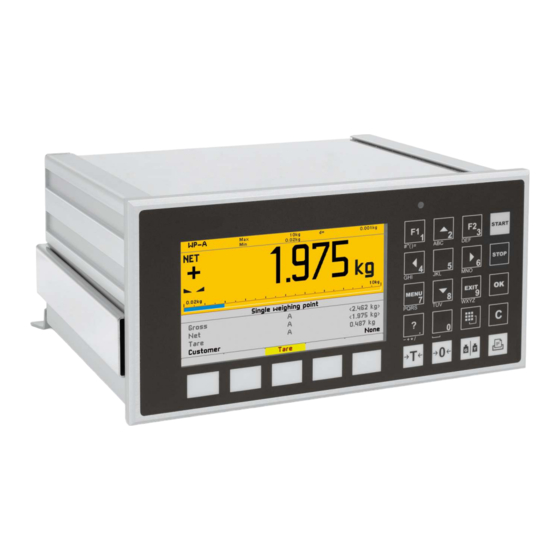
All manuals and user guides at all-guides.com Process Controller Maxxis 4 PR 5500 3 Process controller Process controller General notes The device is equipped with a TFT color graphics display and a function/alphanumeric keypad. With the corresponding application, this device is a powerful system for managing/ documenting weighing and dosing processes. -
Page 13: Communication Protocols
All manuals and user guides at all-guides.com 3 Process controller Process Controller Maxxis 4 PR 5500 Analog test for the weighing electronics Overwrite protection: Via a maximum of 3 CAL switches (two on the main board and one on the... -
Page 14: Housing
All manuals and user guides at all-guides.com Process Controller Maxxis 4 PR 5500 3 Process controller Housing 3.3.1 Housing dimensions The keypad and the display form one unit with the front. A rectangular cut-out is required for the installation. Cable connections are made at the back of the housing. -
Page 15: Housing Dimensions With Strain Relief And Reinforcing Frame
All manuals and user guides at all-guides.com 3 Process controller Process Controller Maxxis 4 PR 5500 3.3.2 Housing dimensions with strain relief and reinforcing frame Front view Side view All dimensions in mm All dimensions in mm Back view The dimensions with the options listed in the table must be observed during installation:... -
Page 16: Control Panel Cut-Out
All manuals and user guides at all-guides.com Process Controller Maxxis 4 PR 5500 3 Process controller 3.3.3 Control panel cut-out The control panel cut-out must be created before the device is installed. +0.5 All dimensions in mm Overview of device front... -
Page 17: Overview Of Connections
All manuals and user guides at all-guides.com 3 Process controller Process Controller Maxxis 4 PR 5500 Description Application keys Indicator keys Menu keys, incl. softkeys For a description of the display and operating elements, refer to Chapter "Display and operating elements" in the PR 5500 operating instructions. -
Page 18: Plug-In Cards
All manuals and user guides at all-guides.com Process Controller Maxxis 4 PR 5500 3 Process controller Connection Description Ethernet Remote operation via VNC LAN interface Software updates (internal) Communication/data exchange: OPC, ModBus-TCP External I/O devices: ModBus-TCP Printer Printer RS‑ ‑ 232... - Page 19 All manuals and user guides at all-guides.com 3 Process controller Process Controller Maxxis 4 PR 5500 Product Description Position PR 5500/13 4 active opto-decoupled inputs Option‑1/FB 4 digital inputs 4 relay outputs with potential-free change- and/or Option‑2 4 digital outputs over contacts For more information, see Chapter 4.5.6.
-
Page 20: Application Licenses
Examples of application packages: Counting, checkweighing, totalizing Automatic dosing and manual illing For product details, see corresponding data sheets/manuals. Applications purchased from Minebea Intec may only be changed as per a source code agreement. Device description 3.6.1 Combinations for options... - Page 21 All manuals and user guides at all-guides.com 3 Process controller Process Controller Maxxis 4 PR 5500 Interface cards: Designation Accessories Code no. Description Chap. Option 1: 2 serial interfaces 2 x RS‑485 in- PR 5500/04 4.5.1 terface Option 2: 2 serial interfaces...
-
Page 22: Device Version Marking
All manuals and user guides at all-guides.com Process Controller Maxxis 4 PR 5500 3 Process controller Designation Accessories Code no. Description Chap. Tilt error cor- PR 5500/87 License (only "Basic" application) rection Alibi memory PR 5500/91 License OPC server PR 5500/92 Use of the PR 1792 OPC server (incl. -
Page 23: Device Installation
All manuals and user guides at all-guides.com 4 Device installation Process Controller Maxxis 4 PR 5500 4 Device installation General notes Before starting work, please read Chapter 2 and follow all instructions. WARNING Warning of hazardous area and/or personal injury All cable connections must be protected from damage. -
Page 24: Emc-Compliant Installation
All manuals and user guides at all-guides.com Process Controller Maxxis 4 PR 5500 4 Device installation Connect the screens to the grounding terminal or the screen clamping rail of the device; see Chapter 4.3. Establish grounding/equipotential bonding between devices/system components;... -
Page 25: 4.4 Hardware Construction
All manuals and user guides at all-guides.com 4 Device installation Process Controller Maxxis 4 PR 5500 4.4 Hardware construction 4.4.1 Main board The following elements are located on the main board: Description Reset key Ethernet port, internal USB connection Slot for optional cards, option 2 Connection for RS‑232 interface, internal... -
Page 26: Leds
All manuals and user guides at all-guides.com Process Controller Maxxis 4 PR 5500 4 Device installation Description Color-graphic display Power supply The color-graphic display is connected to the main board via a ribbon cable. 4.4.2 LEDs Function ADC supply voltage +9 V... -
Page 27: Network Port
All manuals and user guides at all-guides.com 4 Device installation Process Controller Maxxis 4 PR 5500 4.4.3 Network port The device has an internal Ethernet port. NOTICE Damaged data will bring a stop to IT operations. Protect the IT network to prevent unauthorized access. -
Page 28: Usb Connection
Notebook/PC connection Remote operation of the device from a notebook/PC is possible (install VNC software version 3.3.7* on the notebook/PC). * Minebea Intec guarantees the functionality only if this version is used. 4.4.4 USB connection The USB connection is located on the back of the device. - Page 29 All manuals and user guides at all-guides.com 4 Device installation Process Controller Maxxis 4 PR 5500 Connecting to an external PC keyboard 1 2 3 4 5 6 7 8 Keyboard layout PC keyboard Keys MENU Soft Soft Soft Soft...
- Page 30 All manuals and user guides at all-guides.com Process Controller Maxxis 4 PR 5500 4 Device installation [English QWERTY] [Russian QWERTY/йцукен] 4.4.4.3 Barcode scanner A barcode scanner can be connected to the USB interface on the back of the housing as an alternative to an external keyboard.
-
Page 31: Sd Card Slot
SD card. The SD card is only used for storage; it is not used for data transfers. Note: Only SD cards supplied by Minebea Intec may be used. No warranty is given for third- party cards. The following data is saved to the SD card:... - Page 32 All manuals and user guides at all-guides.com Process Controller Maxxis 4 PR 5500 4 Device installation Technical data Description Data Connection Terminal, 5-pin Number of channels Type RS-232, full duplex Transmission rate [bit/s] 300 to 115K2 bit/s Parity None, odd, even...
- Page 33 All manuals and user guides at all-guides.com 4 Device installation Process Controller Maxxis 4 PR 5500 Terminal Block diagram RS-232 4.4.6.1 Connecting a YDP14IS ticket printer via RS-232 The YDP14IS-OCEUV ticket printer can be connected via the internal RS-232 interface.
- Page 34 All manuals and user guides at all-guides.com Process Controller Maxxis 4 PR 5500 4 Device installation Coniguration PR 5500 Printer coniguration [Operating] - [System setup] - [Connect- The printer must be set to "Line Mode" ed devices] - [Printer] - [Interface] - (the factory setting is Page Mode).
- Page 35 All manuals and user guides at all-guides.com 4 Device installation Process Controller Maxxis 4 PR 5500 Coniguration PR 5500 [Operating] - [System setup] - [Weighing points] - [Weighing point X] - [xBPI scale] - [In- terface] - [Built-in RS‑232] Note: For further information, see the platform scale operating instructions.
-
Page 36: Accessories
All manuals and user guides at all-guides.com Process Controller Maxxis 4 PR 5500 4 Device installation Note: For more information, see the manual for the Mettler scale. Accessories 4.5.1 PR 5500/04 2x RS‑ ‑ 485 interface The plug-in card contains two channels. One channel can be used for connecting an IS platform without an external power supply. - Page 37 All manuals and user guides at all-guides.com 4 Device installation Process Controller Maxxis 4 PR 5500 Technical data Description Data Internal connection Contact strip External connection 2 x terminal, 7-pin Number of channels Type RS‑485, full duplex (4‑wire) RS‑485, half duplex (2‑wire)
- Page 38 All manuals and user guides at all-guides.com Process Controller Maxxis 4 PR 5500 4 Device installation PR 5500/04 2x RS-485 interface ↓ 1 2 3 4 5 6 7 8 1 2 3 4 5 6 7 8 ↓ 1 2 3 4 5 6 7 8...
- Page 39 All manuals and user guides at all-guides.com 4 Device installation Process Controller Maxxis 4 PR 5500 Block diagram 2x RS-485 PR 5500/04 PR 5500/04 +24 V B-GNDI RxD/TxD-P B-TxB RxD/TxD-N B-TxA B-RxB B-RxA +24 V A-GNDI RxD/TxD-P A-TxB RxD/TxD-N A-TxA...
- Page 40 All manuals and user guides at all-guides.com Process Controller Maxxis 4 PR 5500 4 Device installation S Function Settings for RS‑ ‑ 485 1 Rx bus termination OFF: not connected ON: (A-RxA 120 Ω A-RxB) 2 Tx pull-up resistor OFF: not connected ON: (A-TxB 1K6 Ω...
- Page 41 All manuals and user guides at all-guides.com 4 Device installation Process Controller Maxxis 4 PR 5500 Switch settings Coniguration ON: S1 [Operating] - [System setup] - [Connected devices] - [PC via EW-Com] - [In- OFF: S2…S4 terface] - [Option 1 RS‑485-A] 4.5.1.3...
- Page 42 All manuals and user guides at all-guides.com Process Controller Maxxis 4 PR 5500 4 Device installation 4.5.1.4 Connecting multiple PR 5500 units to a PC or to an RS-485/RS-232 Converter Connection for the EW-Com protocol. Example: EN-40 Minebea Intec...
- Page 43 All manuals and user guides at all-guides.com 4 Device installation Process Controller Maxxis 4 PR 5500 Switch setting Switch setting Switch setting Coniguration PR 5500-1 PR 5500-2 PR 5500-3 ON: - ON: - ON: S1 [Operating] - [System setup] - [Connected OFF: S1…S8...
- Page 44 All manuals and user guides at all-guides.com Process Controller Maxxis 4 PR 5500 4 Device installation Note: For further information, see the platform scale operating instructions. 4.5.1.6 Connecting digital load cells from type Pendeo® The device can be ported to Pendeo® type digital load cells via the xBPI port and the RS-485 interface (2-wire).
- Page 45 All manuals and user guides at all-guides.com 4 Device installation Process Controller Maxxis 4 PR 5500 ① PR 5500 with PR 5500/04 ② Grounding terminal or screen clamping rail ③ Screen ④ Equipotential bonding conductor Note: For further information, see the installation manuals relating to the load cells and junction boxes.
-
Page 46: Pr 5500/32 2X Rs-232 Interface
All manuals and user guides at all-guides.com Process Controller Maxxis 4 PR 5500 4 Device installation 4.5.2 PR 5500/32 2x RS‑ ‑ 232 interface The plug-in card contains two channels. One channel can be used for connecting an IS platform without an external power supply. The jumper (1) must then be set to A‑24 V or B‑24 V. - Page 47 All manuals and user guides at all-guides.com 4 Device installation Process Controller Maxxis 4 PR 5500 Description Data Cable gauge Max. 1.5 mm Cable length Max. 15 m Cable type Screened twisted pair (e.g., LifYCY 3x2x0.20), 1 pair of wires for ground (GND).
- Page 48 All manuals and user guides at all-guides.com Process Controller Maxxis 4 PR 5500 4 Device installation Note: Refer to Chapter 5.2.3.3 for further information on terminal coding. Block diagram 2x RS-232 PR 5500/32 +24 V B- +24 V B-RTS B-TxD...
- Page 49 All manuals and user guides at all-guides.com 4 Device installation Process Controller Maxxis 4 PR 5500 4.5.2.1 Connecting peripheral devices via RS‑ ‑ 232 Connecting a YDP14IS ticket printer via RS‑232 (see Chapter 4.4.6.1) Connecting a Mettler scale via RS‑232 (see Chapter 4.4.6.4) 4.5.2.2...
-
Page 50: Pr 5500/07 Analog Input And Output
All manuals and user guides at all-guides.com Process Controller Maxxis 4 PR 5500 4 Device installation Note: For further information, see the platform scale operating instructions. 4.5.3 PR 5500/07 analog input and output The plug-in card for the available analog channels has 1 analog output (active) and 1 analog input. - Page 51 All manuals and user guides at all-guides.com 4 Device installation Process Controller Maxxis 4 PR 5500 Description Data Output temperature error <100 ppm/K Output zero point error 0.05% Output max. error <0.1% Load Max. 0 to 500 Ω Potential isolation Cables <150 m, screened...
- Page 52 All manuals and user guides at all-guides.com Process Controller Maxxis 4 PR 5500 4 Device installation Coding for option 1 and option 2 Terminal strip: Insert the coding pin into the slot in the position marked in gray in the image.
-
Page 53: Pr 5500/10 Weighing Electronics Board
All manuals and user guides at all-guides.com 4 Device installation Process Controller Maxxis 4 PR 5500 4.5.4 PR 5500/10 weighing electronics board The weighing electronics board is inserted in the WP A slot. The CAL switch A (1) is located on the board. - Page 54 All manuals and user guides at all-guides.com Process Controller Maxxis 4 PR 5500 4 Device installation Description Data Temperature coef. Zero <0.05 µV/K RTI, <0.004%/10K @ 1 mV/V Temperature coef. Vst <±4.0 ppm/K span Cable length Max. 300 m with PR 6135 Cable type 6‑wire with screen for entire cable and screen for measure-...
- Page 55 4 Device installation Process Controller Maxxis 4 PR 5500 4.5.4.2 Connecting a load cell with a 4-wire cable Note: The colors listed here apply for the Minebea Intec load cell and connection cables of type "PR …" Color code Black Blue...
- Page 56 Process Controller Maxxis 4 PR 5500 4 Device installation 4.5.4.3 Connecting a load cell with a 6-wire cable Note: The colors listed here apply for the Minebea Intec load cell and connection cables of type "PR …" Color code Black Blue...
- Page 57 Connections are made via cable junction box PR 6130/.. using connection cable PR 6135/.. or PR 6136/..Note: The colors listed here apply for the Minebea Intec load cell and connection cables of type "PR …" Color code Black...
- Page 58 All manuals and user guides at all-guides.com Process Controller Maxxis 4 PR 5500 4 Device installation Load cell supply circuit Load resistance of load cell circuit ≥75 Ω, e.g., 8 load cells of 650 Ω each The supply voltage is ixed at U = 12 V and protected against short circuits.
- Page 59 All manuals and user guides at all-guides.com 4 Device installation Process Controller Maxxis 4 PR 5500 4.5.4.5 Testing the measuring circuit A simple test with the load cells connected can be carried out with a multimeter. Note: In the case of an external load cell supply voltage or use of an isolating unit, the internal load cell supply is not relevant.
- Page 60 The center of the external supply voltage (0 ext. supply) should be connected to the device housing to ensure that the voltage reacts symmetrically to 0. The internal supply is not connected. Note: The colors listed here apply for the Minebea Intec load cell and connection cables of type "PR …" Color code Black...
- Page 61 All manuals and user guides at all-guides.com 4 Device installation Process Controller Maxxis 4 PR 5500 ② 0 ext. supply ③ – ext. supply ④ Potential-free ⑤ Screen ⑥ Grounding terminal or screen clamping rail ⑦ Equipotential bonding conductor 4.5.4.7 Connecting an analog weighing platform (CAP…...
- Page 62 All manuals and user guides at all-guides.com Process Controller Maxxis 4 PR 5500 4 Device installation Example: Platform with 4-wire connection The following links should be set directly on the terminal block for platforms with a 4-wire connection: ① from + Supply (+V) to + Sense (+S) ②...
-
Page 63: Pr 5500/12 Digital Inputs And Outputs
All manuals and user guides at all-guides.com 4 Device installation Process Controller Maxxis 4 PR 5500 Example: Platform with 6-wire connection M+ M – V+ S – – ① Screen ② Grounding terminal or screen clamping rail ③ Equipotential bonding conductor 4.5.5... - Page 64 All manuals and user guides at all-guides.com Process Controller Maxxis 4 PR 5500 4 Device installation Technical data Description Data Internal connection Contact strip External connection 2 x terminal, 6-pin 2 x terminal, 4-pin Wire gauge max. 1.5 mm Number of inputs/out-...
- Page 65 All manuals and user guides at all-guides.com 4 Device installation Process Controller Maxxis 4 PR 5500 4.5.5.1 Digital inputs (PR 5500/12) Depicted: Terminal coding and internal circuitry Coding for option 1 and option 2 Terminal strip: Insert the coding pin into the slot in the position marked in gray in the image.
- Page 66 All manuals and user guides at all-guides.com Process Controller Maxxis 4 PR 5500 4 Device installation Note: Refer to Chapter 5.2.3.3 for further information on terminal coding. Example: Connection for PR 5500/12: Digital inputs ① Grounding terminal or screen clamping rail ②...
- Page 67 All manuals and user guides at all-guides.com 4 Device installation Process Controller Maxxis 4 PR 5500 4.5.5.2 Digital outputs (PR 5500/12) Depicted: Terminal coding and internal circuitry Minebea Intec EN-65...
- Page 68 All manuals and user guides at all-guides.com Process Controller Maxxis 4 PR 5500 4 Device installation Coding for option 1 and option 2 Terminal strip: Insert the coding pin into the slot in the position marked in gray in the image.
-
Page 69: Pr 5500/13 Digital Inputs And Outputs
All manuals and user guides at all-guides.com 4 Device installation Process Controller Maxxis 4 PR 5500 Example: Connection for PR 5500/12: Voltage output ① 2.2 kΩ /1 kΩ with 24 V/12 V ② Grounding terminal or screen clamping rail ③ U = 24 V 0.5 A power supply unit... - Page 70 All manuals and user guides at all-guides.com Process Controller Maxxis 4 PR 5500 4 Device installation Technical data Description Data Internal connection Contact strip External connection 2× terminal, 6-pin 2× terminal, 4-pin Wire gauge max. 1.5 mm Number of inputs/out-...
- Page 71 All manuals and user guides at all-guides.com 4 Device installation Process Controller Maxxis 4 PR 5500 4.5.6.1 Digital inputs (PR 5500/13) Depicted: Terminal coding and internal circuitry Minebea Intec EN-69...
- Page 72 All manuals and user guides at all-guides.com Process Controller Maxxis 4 PR 5500 4 Device installation Coding for option 1 and option 2 Terminal strip: Insert the coding pin into the slot in the position marked in gray in the image.
- Page 73 All manuals and user guides at all-guides.com 4 Device installation Process Controller Maxxis 4 PR 5500 4.5.6.2 Digital outputs (PR 5500/13) Depicted: Terminal coding and internal circuitry Minebea Intec EN-71...
- Page 74 All manuals and user guides at all-guides.com Process Controller Maxxis 4 PR 5500 4 Device installation Coding for option 1 and option 2 Terminal strip: Insert the coding pin into the slot in the position marked in gray in the image.
-
Page 75: Pr 5500/17 Digital Inputs And Outputs
All manuals and user guides at all-guides.com 4 Device installation Process Controller Maxxis 4 PR 5500 Example: Connection for PR 5500/13: Voltage output ① 2.2 kΩ /1 kΩ with 24 V/12 V ② Grounding terminal or screen clamping rail ③ U = 24 V 0.5 A power supply unit... - Page 76 All manuals and user guides at all-guides.com Process Controller Maxxis 4 PR 5500 4 Device installation Technical data Description Data Internal connection Contact strip External connection 2× terminal, 6-pin 2× terminal, 4-pin Wire gauge max. 1.5 mm Number of inputs...
- Page 77 All manuals and user guides at all-guides.com 4 Device installation Process Controller Maxxis 4 PR 5500 4.5.7.1 Digital inputs (PR 5500/17) Depicted: Terminal coding and internal circuitry Minebea Intec EN-75...
- Page 78 All manuals and user guides at all-guides.com Process Controller Maxxis 4 PR 5500 4 Device installation Coding for option 1 and option 2 Terminal strip: Insert the coding pin into the slot in the position marked in gray in the image.
- Page 79 All manuals and user guides at all-guides.com 4 Device installation Process Controller Maxxis 4 PR 5500 Example: Connection for PR 5500/17: Digital inputs without potential isolation ① PR 5500/17 ② PLC ③ Power supply Minebea Intec EN-77...
- Page 80 All manuals and user guides at all-guides.com Process Controller Maxxis 4 PR 5500 4 Device installation Example: Connection for PR 5500/17: Digital inputs with potential isolation ① PR 5500/17 ② PLC ③ Power supply EN-78 Minebea Intec...
- Page 81 All manuals and user guides at all-guides.com 4 Device installation Process Controller Maxxis 4 PR 5500 4.5.7.2 Digital outputs (PR 5500/17) Depicted: Terminal coding and internal circuitry Coding for option 1 and option 2 Terminal strip: Insert the coding pin into the slot in the position marked in gray in the image.
-
Page 82: Proibus Dp Interface
All manuals and user guides at all-guides.com Process Controller Maxxis 4 PR 5500 4 Device installation Example: Connection for PR 5500/17: Relay control (power output) ① Inductive load for free-wheel diode ② Grounding terminal or screen clamping rail ③ U = 24 V 0.5 Apower supply unit... - Page 83 All manuals and user guides at all-guides.com 4 Device installation Process Controller Maxxis 4 PR 5500 Technical data Description Data Internal connection Pin strip, 50‑pin External connection 9‑pin D‑Sub female connector in module cover Transfer rate 9.6 kbit/s to 12 Mbit/s, baud rate auto-detection...
- Page 84 All manuals and user guides at all-guides.com Process Controller Maxxis 4 PR 5500 4 Device installation ProiBus connection The device is the only/last slave in the bus: The device is not the only/last slave in the bus: * screen on connector housing * screen on connector housing e.g.: D-Sub bus plug SIMATIC NET PROFIBUS FAST...
-
Page 85: Devicenet Interface
All manuals and user guides at all-guides.com 4 Device installation Process Controller Maxxis 4 PR 5500 Note: Only plug connections with integrated terminating resistors may be used. The terminating resistor must be turned on in the last slave. 4.5.8.1 LEDs... - Page 86 All manuals and user guides at all-guides.com Process Controller Maxxis 4 PR 5500 4 Device installation Technical data Description Data Internal connection Pin strip, 50‑pin External connection 5‑pin terminal (plug-in) in the module cover Transfer rate 125, 250 and 500 kbit/s...
- Page 87 All manuals and user guides at all-guides.com 4 Device installation Process Controller Maxxis 4 PR 5500 DeviceNet terminal Allocation of the 5-pin terminal Pin assignment Signal Color Description Cable sheath Special DeviceNet cable (certiied) 1 -------------------- V– black Negative power supply...
- Page 88 All manuals and user guides at all-guides.com Process Controller Maxxis 4 PR 5500 4 Device installation Module status (MS) LED status Description Comments Module is not initialized. - No power Module has the status "SETUP" or "NW_INIT". Constant green Module is initialized.
- Page 89 All manuals and user guides at all-guides.com 4 Device installation Process Controller Maxxis 4 PR 5500 4.5.9.2 Connection diagram for a master with three slaves PR 5500/.. receives 33 mA from the DeviceNet bus supply. Minebea Intec EN-87...
-
Page 90: Cc-Link Interface
All manuals and user guides at all-guides.com Process Controller Maxxis 4 PR 5500 4 Device installation 4.5.10 CC-Link interface The CC-Link interface card has the type designation PR 1721/65. The ieldbus card contains all functions to provide a complete CC-Link slave with transfer rates up to 10 Mbps. - Page 91 All manuals and user guides at all-guides.com 4 Device installation Process Controller Maxxis 4 PR 5500 CC-Link terminal Allocation of the 5-pole terminal block Pin assignment Signal Description 1 -------------------- Communication RS-485 RxD/TxD (+) 2 -------------------- Communication RS-485 RxD/TxD (–)
-
Page 92: Proinet I/O Interface
All manuals and user guides at all-guides.com Process Controller Maxxis 4 PR 5500 4 Device installation Error (ERR) LED status Description Comments No error No power Constant green Exception error Module has the status "EXCEPTI- ON" The exception error monitoring system closes all open connec- tions to the module. - Page 93 All manuals and user guides at all-guides.com 4 Device installation Process Controller Maxxis 4 PR 5500 Description Data Weight Approx. 33 g Certiicate ProiBus Nutzerorganisation e.V. for HMS Industrial Net- works AB Certiicate no.: Z10931 Report: PN005‑1, 02/12/2007. Note: The ProiNet I/O card PR 1721/76 is supported by software version 2.24 and device serial number 30363xxxxx or higher.
- Page 94 All manuals and user guides at all-guides.com Process Controller Maxxis 4 PR 5500 4 Device installation 4.5.11.1 LEDs PR 1721/66 Identii- Description cation Network status LED Module status LED Link Link/Activity LED Network status (NS) LED status Description Comments Module is oline.
- Page 95 All manuals and user guides at all-guides.com 4 Device installation Process Controller Maxxis 4 PR 5500 LED status Description Comments 3 Hz lashing red Device name error Device name was not deined. 4 Hz lashing red Internal error Module has caused an unrecoverable internal error.
- Page 96 All manuals and user guides at all-guides.com Process Controller Maxxis 4 PR 5500 4 Device installation LED status Description Comments 1 Hz lashing green Module is online (STOP). - There is a connection to the I/ O controller. I/O controller is not operational (STOP status).
-
Page 97: Ethernet/Ip Interface
All manuals and user guides at all-guides.com 4 Device installation Process Controller Maxxis 4 PR 5500 4.5.12 EtherNet/IP interface The EtherNet/IP interface card has the type designation PR 1721/67 or PR 1721/77. The ieldbus card is equipped with a standard RJ-45 socket (PR 1721/67) or two standard RJ-45 sockets (PR 1721/77) for network connection. - Page 98 All manuals and user guides at all-guides.com Process Controller Maxxis 4 PR 5500 4 Device installation Note: The EtherNet/IP card PR 1721/77 is supported by software version 2.24 and device serial number 30363xxxxx or higher. The IP address and subnet mask are set under [Fieldbus parameters] (see the...
- Page 99 All manuals and user guides at all-guides.com 4 Device installation Process Controller Maxxis 4 PR 5500 LED status Description Comments Constant red Exception error Module has the status "EXCEPTI- ON" The exception error monitoring system closes all open connec- tions to the module.
- Page 100 All manuals and user guides at all-guides.com Process Controller Maxxis 4 PR 5500 4 Device installation LED status Description Comments Flashing green Module is online No connection Constant red Critical connection error Duplicate IP address Severe error Flashing red One or more connections has excee- ded the connection time (CIP class 1 or 3).
-
Page 101: Maintenance/Repairs/Soldering Work/Cleaning
Repairs Repairs are subject to inspection and must be carried out at Minebea Intec. In case of defect or malfunction, please contact your local Minebea Intec dealer or service center for repair. When returning the device for repair, please include a precise and complete description of the problem. -
Page 102: Exchanging The Plug-In Cards
All manuals and user guides at all-guides.com Process Controller Maxxis 4 PR 5500 5 Maintenance/repairs/soldering work/cleaning 5.2.3 Exchanging the plug-in cards 5.2.3.1 Safety instructions WARNING Working on the device while it is switched on may have life-threatening consequences. Before a plug-in card is inserted/removed, it is essential that the device is shut down properly (menu [Operating]- [System maintenance]- [Shutdown &... - Page 103 All manuals and user guides at all-guides.com 5 Maintenance/repairs/soldering work/cleaning Process Controller Maxxis 4 PR 5500 Note: The installed plug-in cards can be displayed in the menu [Operating] - [System information] - [Show HW options]. Show hardware options @admin Built-in...
-
Page 104: Replacing The Sd Card
4. Remove (nip of) the corresponding coding nib (5) from the terminal (6). 5. Re-insert the terminal (6) into the terminal strip (4). 5.2.4 Replacing the SD card Note: Only Minebea Intec supplied SD cards may be used. No warranty can be assumed for third-party cards. WP-A 3000g 0.01g –... - Page 105 All manuals and user guides at all-guides.com 5 Maintenance/repairs/soldering work/cleaning Process Controller Maxxis 4 PR 5500 Procedure WARNING Working on the device while it is switched on may have life-threatening consequences. Before a plug-in card is inserted/removed, it is essential that the device is shut down properly (menu [Operating]- [System maintenance]- [Shutdown &...
-
Page 106: Soldering Work
All manuals and user guides at all-guides.com Process Controller Maxxis 4 PR 5500 5 Maintenance/repairs/soldering work/cleaning WP-A 3000g 0.01g 3000g No database found. Do you want to restore the last saved database from the SD card? A selection window opens if no database ile is found in the directory. -
Page 107: Disposal
All manuals and user guides at all-guides.com 6 Disposal Process Controller Maxxis 4 PR 5500 Disposal If the packaging is no longer required, please take it to your local waste disposal facility and/or a reputable disposal company or collection point. The packaging largely consists of environmentally friendly materials which can be used as secondary raw materials. -
Page 108: Technical Data
Current number 30 = Hamburg 252* = April 2010 * Is increment according to the year group table of Minebea Intec. General data The following characteristics are valid after a warm-up time of at least 60 minutes (reference temperature 23 °C). -
Page 109: Supply Voltage Connection 230 V Ac
All manuals and user guides at all-guides.com 7 Technical data Process Controller Maxxis 4 PR 5500 7.3.4 Supply voltage connection 230 V AC Supply voltage = 100 to 240 V +10%/-15%, 50/60 Hz Max. power consumption 14 W/32 VA Primary fuse 2 x 1 AT;... -
Page 110: Rf Interference Suppression
All manuals and user guides at all-guides.com Process Controller Maxxis 4 PR 5500 7 Technical data Mains inputs Fast transient disturbances (Burst) EN 61000-4-4 2 kV Peak voltages (surge) 1.2/50 µs EN 61000-4-5 1/2 V Conducted disturbances by high fre-... -
Page 111: Appendix
All manuals and user guides at all-guides.com 8 Appendix Process Controller Maxxis 4 PR 5500 8 Appendix Certiicates Ser. no. Description Document no. EU-Declaration of Conformity MEU17035 Declaration of Conformity MDC17004 Parts Certiicate PTB DE.18-PC-PTB002 Certiicate of Conformance NTEP 18-029 EU-type examination certiicate NMi T11379 The documents listed in the table can be found on the PR 5500 CD. - Page 112 All manuals and user guides at all-guides.com Published by Minebea Intec GmbH | Meiendorfer Strasse 205 A | 22145 Hamburg, Germany Phone: +49.40.67960.303 | Email: info@minebea-intec.com www.minebea-intec.com...
Need help?
Do you have a question about the Maxxis 4 and is the answer not in the manual?
Questions and answers