
Related Manuals for Delta OHM HD2178.1


Summary of Contents for Delta OHM HD2178.1
- Page 1 English Operating manual RTD / thermocouple thermometers HD2178.1 – HD2178.2 Companies / Brands of GHM www.deltaohm.com Keep for future reference.
-
Page 2: Table Of Contents
CONTENTS INTRODUCTION ..............................3 KEYBOARD AND MENU DESCRIPTION ......................8 THE PROBES ................................14 ..........................14 EMPERATURE MEASUREMENT Calibration of the RTD and thermocouple temperature probe in line with the instrument ........14 Instructions to connect the TP47 connector for 4-wire Pt100, Pt1000 and Ni1000 probes ........15 Direct connection of 4 wire Pt100 sensors ......................17 WARNINGS AND OPERATING INSTRUCTIONS ....................18 INSTRUMENT SIGNALS AND FAULTS ......................19... -
Page 3: Introduction
The HD2178.1 and HD2178.2 models are fitted with an RS232C serial port and can transfer the ac- quired measurements in real time to a PC or to a portable printer. - Page 4 RTD - Thermocouple Thermometer HD2178.1 - 4 - HD2178 V2.3...
- Page 5 HD2178.1 1. Input for thermocouple, standard miniature connector. 2. Input for probes, 8-pole DIN45326 connector. 3. Input for external power supply connector. 4. Battery symbol: displays the battery charge level. 5. Function indicators. 6. Secondary display line. 7. HOLD/ key: freezes the measurement during normal operation; in the menu, increases the current value.
- Page 6 RTD – Thermocouple Thermometer HD2178.2 - 6 - HD2178 V2.3...
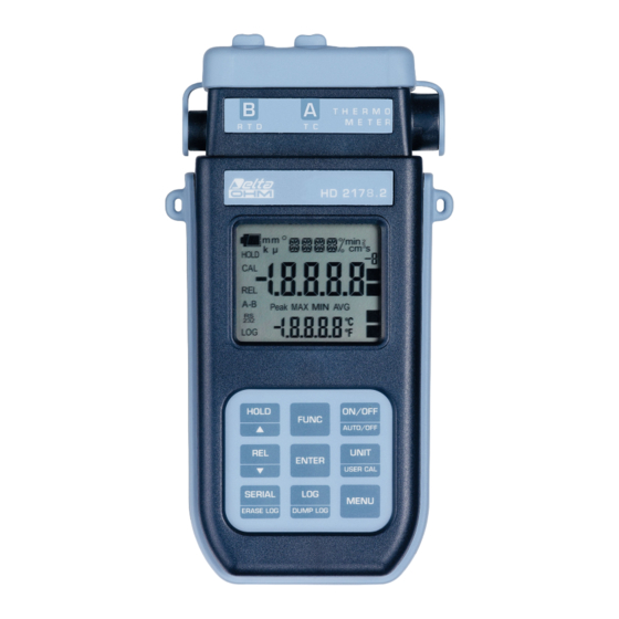
- Page 7 HD2178.2 1. Input for thermocouple, standard miniature connector. 2. Input for probes, 8-pole DIN45326 connector. 3. External auxiliary power supply connector input. 4. Battery symbol: displays the battery charge level. 5. Function indicators. 6. Secondary display line. 7. HOLD/ key: freezes the measurement during normal operation; in the menu, increases the current value.
-
Page 8: Keyboard And Menu Description
KEYBOARD AND MENU DESCRIPTION Foreword The instrument keyboard is composed of single-function keys, like the MENU key, and double- function keys such as the ON-OFF/Auto-OFF key. In the double-keys, the function in the upper part is the “main function”, while the one in the bottom part is the “secondary function”. - Page 9 This setting changes the information displayed and the immediate print of data (SERIAL key). The data recorded using the LOG function (HD2178.2) and sent to the printer or PC through the serial port using the SERIAL function (HD2178.1 and HD2178.2), keep the chosen unit of measurement and display it.
- Page 10 ENTER key In the menu, the ENTER key confirms the displayed parameter and then goes to the next one. REL/ In measurement mode, it displays the difference between the current value and that measured on pressing the key. The REL message appears on the display; press the key again to return to the cur- rent measurement.
- Page 11 When turned on, the temperature probes direct 4-wire Pt100, the Pt1000 and the Ni1000 display the message "CH_B_NO_SER_NUM" (no probe serial number); in this case the probe type must be entered manually. Select Probe type using the MENU key, CH_B and then the type of probe used with the arrow keys;...
- Page 12 When the LOG key is pressed after the MENU key, the transfer of the logged data on the serial port is started. Please see the paragraph dedicated to data transfer on page 25. SERIAL key - only HD2178.1 SERIAL/EraseLOG key - only HD2178.2 In measurement mode, this function starts and stops the data transfer to the RS232C serial output.
- Page 13 >>> Erase memory - only HD2107.2 When pressed after the MENU key, the SERIAL/ERASE LOG key permanently erases all the data contained in the instrument's memory. - 13 - HD2178 V2.3...
-
Page 14: The Probes
THE PROBES Input A accepts K, J, T, N or E thermocouple temperature probes. The thermocouple type is set up by menu. The connector contacts of thermocouple probe are polarized, they have to be put into the miniature connector placed in the instrument on the right way. Usually the probes are marked with the symbol + and -: these symbols have to correspond to the relevant symbols placed on the rubber protection of the instrument. -
Page 15: Instructions To Connect The Tp47 Connector For 4-Wire Pt100, Pt1000 And Ni1000 Probes
Instructions to connect the TP47 connector for 4-wire Pt100, Pt1000 and Ni1000 probes All Delta Ohm probes are provided with a connector. The HD2178.1 and HD2178.2 instruments also work with 4-wire direct Pt100, 2-wire Pt1000 and Ni1000 probes manufactured by other pro- ducers: for the instrument connection is prescribed the TP47 connector to which the probe's wires should be welded. - Page 16 The instructions to connect the Platinum or Nickel probe to the module are provided below. The module is supplied complete with fairlead and gasket for 5mm maximum diameter cables. Do the following to open the module and connect a probe: Unscrew the fairlead and extract the gasket, remove the label using a cutter, unscrew the ring on the opposite side as illustrated in the figure: Open the two module shells: the printed circuit to which the probe must be connected is housed in-...
-
Page 17: Direct Connection Of 4 Wire Pt100 Sensors
Sensor TP47 card connection Jumper to close Ni1000 Ni1000 2 wires Ensure the welds are clean and perfect. Once the welding operation is complete, close the two shells, insert the gasket in the module, and screw the fairlead and the ring. At the other end of the module, enter the ring with the O-Ring. -
Page 18: Warnings And Operating Instructions
WARNINGS AND OPERATING INSTRUCTIONS 1. Do not expose the probes to gases or liquids that could corrode the material of the sensor or the probe itself. Clean the probe carefully after each measurement. 2. Do not bend the probe connectors or force them upward or downward. 3. -
Page 19: Instrument Signals And Faults
INSTRUMENT SIGNALS AND FAULTS The following table lists all error indications and information displayed by the instrument and sup- plied to the user in different operating situations: Display indications Explanation This appears if the probe has already been detected by the instrument, but is disconnected. - Page 20 The following table reports the indications provided by the instrument as they appear on the display, together with their description. Display indications Explanation >>> CAL_MODE >>> KEY_UNIT calibration mode >>> press UNIT to start a new user calibration FOR_NEW_USER CAL_ >>>_LOG_DUMP_or_ERAS transfer or erase data type of probe connected...
-
Page 21: Low Battery Warning And Battery Replacement
LOW BATTERY WARNING AND BATTERY REPLACEMENT The battery symbol on the display constantly shows the battery charge status. To the extent that batteries have dis- charged, the symbol "empties". When the charge decreases still further it starts blinking… In this case, batteries should be replaced as soon as possible. If you continue to use it, the instrument can no longer ensure correct measurement. -
Page 22: Instrument Storage
ALFUNCTIONING UPON TURNING ON AFTER BATTERY REPLACEMENT After replacing the batteries, the instrument may not restart correctly; in this case, repeat the opera- tion. After disconnecting the batteries, wait a few minutes in order to allow circuit condensers to discharge completely; then reinsert the batteries. ARNING ABOUT BATTERY USE •... -
Page 23: Serial Interface And Usb
SERIAL INTERFACE AND USB The HD2178.1 and HD2178.2 instruments are fitted with an electrically isolated RS-232C serial in- terface; the HD2178.2 also has an USB 2.0 interface. The following serial cables can be used: • HD2110CSNM: serial connection cable with 8-pole MiniDin connector on one end and 9-pole Sub D connector on the other end;... - Page 24 Command Response Description M=RTD + Thermocouple K Model description SN=12345678 Instrument serial number Firm.Ver.=01-00 Firmware version Firm.Date=2004/06/15 Firmware date cal 0000/00/00 00:00:00 Calibration date and time Probe=Tc K Type of thermocouple probe connected to input A Probe=Sicram Pt100 Type of probe connected to input B Probe SN=11119999 Serial number of probe connected to input B Probe cal.=2004/01/12...
-
Page 25: Storing And Transferring Data To A Personal Computer
STORING AND TRANSFERRING DATA TO A PERSONAL COMPUTER The HD2178.1 and HD2178.2 instruments can be connected to a personal computer via an RS232C serial port or USB 2.0 port, and exchange data and information through the DeltaLog9 software running in a Windows operating environment. Both models can send in real time input measured values directly to a PC, through the PRINT function;... -
Page 26: The Print Function
PRINT FUNCTION The PRINT function sends the measurements taken in real time by the instrument inputs directly to a PC or a printer. Print data units of measurements are the same as those used on the display. The function is started by pressing SERIAL. The time interval between two consecutive prints can be set from 1 second to 1 hour (please see the Print and log interval menu item on page 10). -
Page 27: Connection To A Pc
SERIAL PORT OF THE INSTRUMENT 1. The measurement instrument must be switched off. 2. Using the Delta Ohm HD2110CSNM or C.206 cable, connect the measurement instrument to the first free RS232C (COM) or USB serial port of the PC. 3. Turn on the instrument and set the baud rate to 38400 (MENU >> ENTER until the Baud Rate parameter >>... -
Page 28: Notes About Working And Operative Safety
NOTES ABOUT WORKING AND OPERATIVE SAFETY Authorized use The technical specifications as given in chapter "TECHNICAL CHARACTERISTICS" must be ob- served. Only the operation and running of the measuring instrument according to the instructions given in this operating manual is authorized. Any other use is considered unauthorized. General safety instructions This measuring system is constructed and tested in compliance with the EN 61010-1:2010 safety regulations for electronic measuring instruments. -
Page 29: Instrument Technical Characteristics
INSTRUMENT TECHNICAL CHARACTERISTICS Instrument Dimensions (Length x Width x Height) 185x90x40mm Weight 470g (complete with batteries) Materials ABS, rubber Display 2x4½ digits plus symbols Visible area: 52x42mm Operating conditions Working temperature -5…50°C Storing temperature -25…65°C Working relative humidity 0…90%RH without condensation Protection degree IP66 Power Supply... - Page 30 Connections Input module for the probes 8-pole male DIN45326 connector RS232 serial interface 8-pole MiniDin connector USB interface (only HD2178.2) Mini-USB type B connector Mains adapter (cod. SWD10) 2-pole connector (positive at centre) Measurement of temperature by Instrument – RTD sensors Pt100 measurement range -200…+650°C Pt1000 measurement range...
-
Page 31: Technical Data Of Probes And Modules In Line With The Instrument
TOLERANCE CLASSES OF THERMOCOUPLES Tolerances according to IEC 60584-2 standard. The values refer to thermocouples with reference junction at 0 °C. Tolerance class 1 Tolerance class 2 Tolerance class 3 Temperature Temperature Temperature Type of Tolerance Tolerance Tolerance range range range thermocouple (°C) -
Page 32: Temperature Probes Pt100 Sensor Using Sicram Module
Pt100 EMPERATURE PROBES SENSOR USING SICRAM MODULE Model Type Application range Accuracy ±0.25°C (-196°C…+300°C) Immersion -196°C…+500°C TP472I ±0.5°C (+300°C…+500°C) TP472I.0 Immersion -50°C…+300°C ±0.25°C 1/3 DIN – Thin Film ±0.25°C (-50°C…+300°C) TP473P.I Penetration -50°C…+400°C ±0.5°C (+300°C…+400°C) TP473P.0 Penetration -50°C…+300°C ±0.25°C 1/3 DIN - Thin Film TP474C.0 Contact -50°C…+300°C... -
Page 33: Order Codes
ORDER CODES HD2178.1 Kit including the instrument HD2178.1, 4 1.5V alkaline batteries, operating man- ual, case and DeltaLog9 software. The probes and the cables must be ordered separately. HD2178.2 Kit including the HD2178.2 datalogger, 4 1.5V alkaline batteries, operating man- ual, case and DeltaLog9 software. - Page 34 Any kind of thermocouple probes with standard miniature connector described in the price-list can be connected to these instruments. DELTA OHM metrology laboratories LAT N° 124 are accredited by ACCREDIA for Tem- perature, Humidity, Pressure, Photometry / Radiometry, Acoustics and Air Velocity. They can supply calibration certificates for the accredited quantities.
- Page 36 All DELTA OHM instruments are subject to accurate testing, and are guaranteed for 24 months from the date of purchase. DELTA OHM will repair or replace free of charge the parts that, within the warranty period, shall be deemed non efficient according to its own judgement. Complete replacement is excluded and no damage claims are accepted.
- Page 37 GHM GROUP – Delta OHM | Delta Ohm S.r.l. a socio unico Via Marconi 5 | 35030 Caselle di Selvazzano | Padova | ITALY Phone +39 049 8977150 | Fax +39 049 635596 www.deltaohm.com | info@deltaohm.com The quality level of our instruments is the result of the constant development of the product. This may produce some differences between the information written in this manual and the instrument you have purchased.
- Page 38 GHM GROUP – Delta OHM | Delta Ohm S.r.l. a socio unico Via Marconi 5 | 35030 Caselle di Selvazzano | Padova | ITALY Phone +39 049 8977150 | Fax +39 049 635596 www.deltaohm.com | info@deltaohm.com V2.3 28/08/2017...
Need help?
Do you have a question about the HD2178.1 and is the answer not in the manual?
Questions and answers