Table of Contents

Related Manuals for Dometic Go Power GP-TS-50


Summary of Contents for Dometic Go Power GP-TS-50
- Page 1 TRANSFER SWITCH User Manual GP-TS-50 © 2022 Go Power! Worldwide Technical Support and Product Information gpelectric.com Go Power! | Dometic 201-710 Redbrick Street Victoria, BC, V8T 5J3 Tel: 1.866.247.6527 MOBI_MAN_GP-TS-50_RevE...
-
Page 2: Table Of Contents
CONTENTS 2. INTRODUCTION ..............3 3. INSTALLATION ............... 3 3.1 DISCONNECT POWER................3 3.2 MOUNTING LOCATION ................3 3.3 ELECTRICAL PREPARATION ................ 4 3.4 MOUNTING ....................4 3.5 ELECTRICAL PREPARATION ................ 4 3.5.1 INSTALLATION BETWEEN POWERCORD AND GENERATOR (CONFIGURATION A) ..............5 3.5.2 INSTALLATION BETWEEN INVERTER AND ALTERNATING SOURCE (CONFIGURATION B) .............. -
Page 3: Introduction
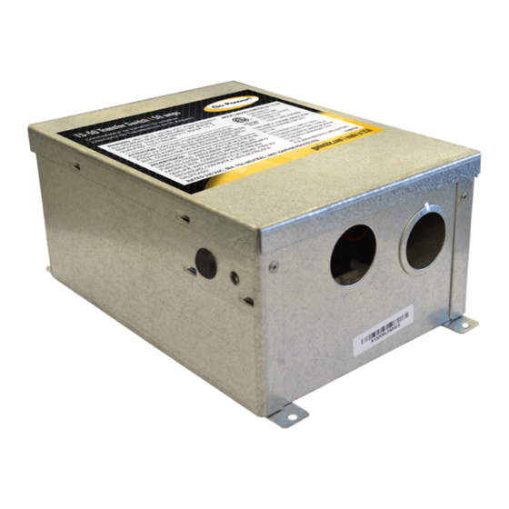
2. INTRODUCTION The Go Power!™ Transfer Switch 50 (TS-50) provides automatic power switching between two separate 120 volt AC input sources, these sources will each contain two 120 volt 50 amp inputs or a single 120 volt 50 amp input. Sources can include power cords, generators or onboard inverters. -
Page 4: Electrical Preparation
INSTALLATION 3.3 ELECTRICAL PREPARATION Use knockouts 12, 5, and 6 when installing the TS-50. Do not use knockouts 3, 4, 7, and 8 when preparing the TS-50 for installation. 3.4 MOUNTING Mount the TS-50 with screws through holes provided in bottom corners of the can. The unit should be screwed to a solid surface firmly enough to hold its weight during vehicle operation. -
Page 5: Installation Between Powercord And Generator
INSTALLATION H. In some applications it may be desirable to feed a 120 volt supply, such as an inverter, into both hot legs of a transfer switch, so that the 120 volt supply can operate the entire RV load. Although discretion is advised in designing this into the system, it is acceptable, as long as the connection to both hot legs is accomplished on the input side of the transfer switch. -
Page 6: Installation Between Inverter And Alternating Source
INSTALLATION 3.5.2 Installation Between Inverter and Alternating Source (Configuration B) For installation between an inverter (default) and another power supply (dominant), such as the output from a prior powercord/ generator transfer switch, connect the inverter neutral to “powercord’ lug labeled NEUTRAL WHT, and connect the inverter hot to “powercord”... - Page 7 INSTALLATION DIAGRAM 1 gpelectric.com | [page 7]...
- Page 8 INSTALLATION [page 8] | gpelectric.com...
-
Page 9: Operation
4. OPERATION READ AND FOLLOW ALL SAFETY INSTRUCTIONS! 1. Plug in the powercord. If the main panel circuit breakers are switched on, RV load should operate normally. Unplug the powercord. 2. Start the generator. There is a preprogrammed 20-30 second delay in the transfer switch. -
Page 10: General Low Voltage
TROUBLESHOOTING 5.2 GENERAL LOW VOLTAGE Low voltage can be caused by low voltage conditions such as an RV park with inadequate wiring for crowded camper conditions where everyone’s electricity suffers (brownout). In this case a voltmeter will be helpful and will show a low voltage reading from the park receptacle, even before the RV is plugged in. -
Page 11: Hi-Pot Testing
6. HI-POT TESTING such a manner that the wiring will interfere with the physical operation of the relay. Visually inspect for free operation of the relay(s). 6. HI-POT TESTING (MANUFACTURING COMPANIES ONLY) NOTE: If the hi-pot test is performed from the plug on the powercord, the test may only hi-pot the cord itself;... -
Page 12: Generator Note
7. GENERATOR NOTE shorted plug. If the test passes, turn on the main breaker, and turn on all branch breakers except one. Retest each branch circuit individually until the shorted circuit is isolated. Repair the fault and retest. The hi-pot test is successful when there are no more fault indications. -
Page 13: Warranty Return Procedure
10. WARRANTY Go Power! warrants this product for a period of five (5) years from the date of shipment from its factory. This warranty is valid against defects in materials and workmanship for the five (5) year warranty period. It is not valid against defects resulting from, but not limited to: •... - Page 14 © 2022 Go Power! Worldwide Technical Support and Product Information gpelectric.com Go Power! | Dometic 201-710 Redbrick Street Victoria, BC, V8T 5J3 Tel: 1.866.247.6527 MOBI_MAN_GP-TS-50_RevE...
Need help?
Do you have a question about the Go Power GP-TS-50 and is the answer not in the manual?
Questions and answers