
Related Manuals for CLIVET MSRT-XSC3


Summary of Contents for CLIVET MSRT-XSC3
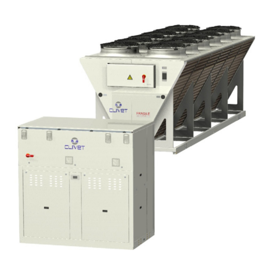
- Page 1 Installation and operating manual Air-cooled liquid chiller in two sections MSRT-XSC3 + CEV-XT 90.4-240.4 M04W40N16-02 11-12-19...
- Page 2 Yours faithfully. CLIVET Spa The data contained in this manual is not binding and may be changed by the manufacturer without prior notice. Reproduction, even is part, is FORBIDDEN © Copyright - CLIVET S.p.A. - Feltre (BL) - Italia...
-
Page 3: Table Of Contents
Index of contents General description Reception Positioning Water connections Refrigeranting connections Electrical connections Start-up Control Maintenance Accessories Decommissioning Residual risks General technical date Dimensional drawings M04W40N16-02 MSRT-XSC3 + CEV-XT 90.4-240.4... -
Page 4: General Description
Contact a certified service agent. Use original spares parts only. Using the unit in case of breakdown or malfunction: • voids the warranty • it may compromise the safety of the unit • may increase time and repair costs MSRT-XSC3 + CEV-XT 90.4-240.4 M04W40N16-02... - Page 5 1.14 Assistance request Note data from the serial number label and write them in the chart on side, so you will find them easily when needed. Series Size Serial number Year of manufacture Electrical wiringdiagram M04W40N16-02 MSRT-XSC3 + CEV-XT 90.4-240.4...
-
Page 6: Reception
Align the barycenter to the lifting point Use all the lifting brackets (see the dimensional section) Gradually bring the lifting belts under tension, making sure they are positioned correctly. 10. Before starting the handling, make sure that the unit is stable. MSRT-XSC3 + CEV-XT 90.4-240.4 M04W40N16-02... - Page 7 Keep packing material out of children’s reach it may be dangerous. Recycle and dispose of the packaging material in conformity with local regulations. Supports for handling: remove after the handling. Remove the coil protective mesh before the start-up M04W40N16-02 MSRT-XSC3 + CEV-XT 90.4-240.4...
-
Page 8: Positioning
HIGH PRESSURE (in summer) or LOW PRESSURE (in winter) 3.3 Saftey valve gas side The installer is responsible for evaluating the opportunity of installing drain tubes, in conformity with the local regulations in force (EN 378). MSRT-XSC3 + CEV-XT 90.4-240.4 M04W40N16-02... - Page 9 3.4 AxiTop 3.5 Functional spaces 1500 1500 1500 1500 1500 1500 1200 1200 full height wall: standard compliance spaces low height wall: reduced space 3.6 Anti-vibration mount support For details see: 10 Accessories p. 53 M04W40N16-02 MSRT-XSC3 + CEV-XT 90.4-240.4...
-
Page 10: Water Connections
(for example in systems where some circuits are bypassed in particular situations). 4.5 Minimum system water content Minimum system water volumes have to be satisfied to avoid continuous compressor switching on and off. MSRT-XSC3 + CEV-XT 90.4-240.4 M04W40N16-02... - Page 11 Flow Switch water temperature probe System load safety pressure switch differential pressure switch pressure gauge antivibration joints non-return valve piping support Pump exchanger chemical cleaning bypass safety valve Cleaning system bypass shut-off valve vent filter M04W40N16-02 MSRT-XSC3 + CEV-XT 90.4-240.4...
- Page 12 Isolate the pipes to avoid heat dispersions and formation of condensate. Leave various point of service free (wells, vent-holes etc). Neglecting the washing will lead to several filter cleaning interventions and at worst cases can cause damages to the exchangers and the other parts. MSRT-XSC3 + CEV-XT 90.4-240.4 M04W40N16-02...
- Page 13 When the temperature of the water to be heated is particularly low, it is wise to insert a flow-rate control valve into the system water circuit, in order to maintain the temperature at the recovery output at above 35°C and thus avoid the condensation of the refrigerant into the partial energy recovery device. UNIT M04W40N16-02 MSRT-XSC3 + CEV-XT 90.4-240.4...
-
Page 14: Refrigeranting Connections
• Install antivibration material between the brackets and the pipes so as to prevent the transmission of vibrations • avoid the passage in particularly silent environments MSRT-XSC3 + CEV-XT 90.4-240.4 M04W40N16-02... - Page 15 (if the unit is not fitted with taps with service fittings) GAS 1 GAS 2 GAS 1 GAS 2 1/100 1/100 Gas (x 2) Liquid (x 2) 4 mt Max 5 mt Max 10 mt 4 mt M04W40N16-02 MSRT-XSC3 + CEV-XT 90.4-240.4...
- Page 16 2: up to PS x 1,43 law (as according to UNI-EN 378-2) CAUTION: EXPLOSION DANGER Spray using a leak detector spray taps and pipes and check if bubbles are present (gas leaks). Discharge the nitrogen from the unit. MSRT-XSC3 + CEV-XT 90.4-240.4 M04W40N16-02...
- Page 17 Once charging is complete, open the gas tap so that the unit is ready to be started. 5.11 Adding oil Consider adding oil if the connection pipes are particularly long. Check the oil level of the compressor in the indicator or in the Schrader plug. M04W40N16-02 MSRT-XSC3 + CEV-XT 90.4-240.4...
-
Page 18: Electrical Connections
Do not lay the cables parallel to other cables, cable crossings are possible, only if laid at 90°. Connect the screen to the ground, only if there aren’t disturbances. Guarantee the continuity of the screen during the entire extension of the cable. Respect impendency, capacity and attenuation indications. MSRT-XSC3 + CEV-XT 90.4-240.4 M04W40N16-02... - Page 19 Respect the minimum distance from the ground to allow the entry of the power line. The cable must not touch the compressor and the refrigerant piping (they reach high temparatures). 6.5 Connections performer by customer M04W40N16-02 MSRT-XSC3 + CEV-XT 90.4-240.4...
- Page 20 MSRT-XSC3 + CEV-XT 90.4-240.4 M04W40N16-02...
- Page 21 2 x 30 x 5 Max. bar Cu width (mm) Tightening torque (Nm) 6.7 Remote ON-OFF Do not perform short On Off cycles Do not use the remote On Off with thermoregulation function. Y E S N O ! M04W40N16-02 MSRT-XSC3 + CEV-XT 90.4-240.4...
- Page 22 12. write and run the command Ping 192.168.1.42 13. the message, connection is OK, will appear when successful 14. enter the browser (Crhome, Firefox ecc) 15. write and run the command http:/192.168.1.42 16. Userid = WEB 17. Password = SBTAdmin! MSRT-XSC3 + CEV-XT 90.4-240.4 M04W40N16-02...
- Page 23 KNX bus, max 350 mt twisted pair with shield, ø 0,8 mm EIB/KNX cable marking recommende PSX - Mains power supply unit pwer supply unit N125/11 5WG1 125-1AB11 AC 120...230V, 50...60Hz KNX bus, max 350 mt M04W40N16-02 MSRT-XSC3 + CEV-XT 90.4-240.4...
- Page 24 • The cable must have insulation features and non-flame propagation in accordance with applicable regulations. • The RS485 serial line must be kept as far away as possible from sources of electromagnetic interference. MSRT-XSC3 + CEV-XT 90.4-240.4 M04W40N16-02...
- Page 25 LED BUS communication with BACnet green communication ok green ready for communication yellow software ok but communication with AP1 yellow startup down flashing: software error BACnet server down fixed: hardware error restart after 3 sec M04W40N16-02 MSRT-XSC3 + CEV-XT 90.4-240.4...
-
Page 26: Start-Up
17. loaded system + possible glycol solution + corrosion inhibitor 18. system under pressure 19. vented system 20. refrigerant circuit visual check 21. earthing connection 22. power supply features 23. electrical connections provided by the customer MSRT-XSC3 + CEV-XT 90.4-240.4 M04W40N16-02... - Page 27 Check the voltage and line frequency values which must be within the limits: 400/3/50 +/- 10% Check and adjust the phase balance as necessary: it must be lower than 2% Example Working outside of these limits can cause irreversible damages and voids the warranty. M04W40N16-02 MSRT-XSC3 + CEV-XT 90.4-240.4...
- Page 28 The above-described operating conditions must be considered outside the operating limits. In the event of compressor breakdown, due to operating in the above-mentioned conditions, the guarantee will not be valid and Clivet spa declines any responsibility.
- Page 29 Demand limit Demand limit Confirm Press 3 sec. Select Local connections Path: Main Menu / Unit parameters / Demand limit Parameters Short description description P0200 setpointdemandlimit Parameter setting of the value % of demand limit M04W40N16-02 MSRT-XSC3 + CEV-XT 90.4-240.4...
- Page 30 AirAtSptHigH P0613 AirAtSptHigH external air temperature value where the calculated setpoint takes on the value given by HSptHigh P0606 / P0609: Coooling P0610 / P0613: Heating MSRT-XSC3 + CEV-XT 90.4-240.4 M04W40N16-02...
- Page 31 Value of the WR control signal corresponding to the correction of the set Heating equal to P0615 P0620 SWRMinH Value of the WR control signal corresponding to the correction of the set Heating equal to 0 P0616 / P0618: Cooling P0615, P0619, P0620: Heating M04W40N16-02 MSRT-XSC3 + CEV-XT 90.4-240.4...
- Page 32 There must be suitable arresters to protect the serial lines from the effects of atmospheric discharges • The data line must be kept separate from the power conductors or powered at different voltage values and away from possible sources of electrical interference MSRT-XSC3 + CEV-XT 90.4-240.4 M04W40N16-02...
- Page 33 Temperature Offset the master sum or subtract, depending on the way you set, in order of priority, to the set point of P0657 LNOffset the slave P0658 TypeRegMS Operation mode: 0=mode A; 1=mode B; 2=mode C P0659 LNAddress ProcessBus address unit M04W40N16-02 MSRT-XSC3 + CEV-XT 90.4-240.4...
- Page 34 (for ex. Condensing circuit + direct expansion unit) Certification of setting in service: • for all the units Periodical verifications: • to be executed with the frequency indicated by the Manufacturer (see the “maintenance inspections” paragraph) MSRT-XSC3 + CEV-XT 90.4-240.4 M04W40N16-02...
-
Page 35: Control
1 = 1 compr. On circuit 2 = 0 compr. On Heating capacity 8.3 Keys Symbol Name description Info Main menu Alarm Alarm display Exit Cancel Previous level Keyboard settings Increases value Down Decreases value Confirm Enter Password M04W40N16-02 MSRT-XSC3 + CEV-XT 90.4-240.4... - Page 36 Enable by remote switch P0855 SetPointECOCooling Economic summer SetPoint P0577 SetPointHeating Setpoint Heat P0578 2SetPointHeating 2° Setpoint Heat P0579 SetPointECOHeating Economic winter SetPoint P0640 SetPointRecover Recovery Set Point P0580 ACSSetPoint domestic hot water set point MSRT-XSC3 + CEV-XT 90.4-240.4 M04W40N16-02...
- Page 37 Option config P0052=1 Press 3 sec. Select Local connections * Unit Parameters menu is displayed 8.8 Display the status Step Display Action Menu/Variable Keys Notes Press Main menu Select Machine State Select General, circuit, ecc.. Exit M04W40N16-02 MSRT-XSC3 + CEV-XT 90.4-240.4...
- Page 38 EEV PID 1 controller status EEV PID 2 controller status EEV PID 3 controller status Source EEV 1 Source EEV 2 User-side EEV Bitmap Alarms 1.1 Bitmap Alarms 2.1 Bitmap Alarms 3.1 Bitmap Alarms 4.1 MSRT-XSC3 + CEV-XT 90.4-240.4 M04W40N16-02...
- Page 39 Source System Load 1180 High Pressure 1.1 1181 Compressor 1.1 Protection 1182 Compressor 2.1 Protection 1184 Source Fan 1.1 Protection 2180 High Pressure 1.2 2181 Compressor 1.2 Protection 2183 Compressor 2.2 Protection 2184 Source Fan 1.2 Protection M04W40N16-02 MSRT-XSC3 + CEV-XT 90.4-240.4...
- Page 40 Source Pump 2.1 Command 2303 Compressor 1.2 Command 2304 Compressor 2.2 Command 2305 Liquid Injection 1.2 2306 Liquid Injection 2.2 2307 RecValve Battery 1.2 2308 RecValve Chiller 1.2 2309 RecValve Recovery 1.2 2310 Reversing Cycle Valve 1.2 MSRT-XSC3 + CEV-XT 90.4-240.4 M04W40N16-02...
- Page 41 Alarm list detail Press 3 sec. Password Enter password Alarm list detail Press Alarm list Select Alarm Reset Select Executed Press 3 sec. Password management Select Log off For details see: General list of alarms M04W40N16-02 MSRT-XSC3 + CEV-XT 90.4-240.4...
- Page 42 Recovery Inverter Protection Recovery side inverter overload protection Recovery ee0100 TimeOutModPOL98U POL98U module disconnected HW TimeOut ee0101 TimeOutModPOL98U_2 POL98U module disconnected HW TimeOut ee0102 TimeOutModPOL96U POL96U module disconnected HW TimeOut ee0103 TimeOutModPOL945 POL945 module disconnected HW TimeOut MSRT-XSC3 + CEV-XT 90.4-240.4 M04W40N16-02...
- Page 43 Compressor 3 envelope alarm Circuit 1 ee1055 Alarm Inverter 1 Inverter 1 in alarm Inverter DFS ee1056 Alarm missing comunication inv1 Inverter 1 Modbus communication error Inverter DFS ee1057 Timeout comunication inv1 Inverter 1 communication timeout Inverter DFS M04W40N16-02 MSRT-XSC3 + CEV-XT 90.4-240.4...
- Page 44 Inverter 1 communication timeout Inverter APY ee2040 Alarm Inverter 2 Inverter 2 in alarm Inverter APY ee2041 Alarm missing comunication inv2 Inverter 2 Modbus communication error Inverter APY ee2042 Timeout comunication inv2 Inverter 2 communication timeout Inverter APY MSRT-XSC3 + CEV-XT 90.4-240.4 M04W40N16-02...
- Page 45 Vacuum Circuit Vaacum Alarm Circuit 1 FF1046 LimLp Low pressure limit Circuit 1 ff1047 DFRForced Defrost Forced Circuit 1 ff1048 DFRWaterTLow Low water temperature for defrost operation Circuit 1 ff1049 DFRTimeMax Defrost Maximum Time Circuit 1 M04W40N16-02 MSRT-XSC3 + CEV-XT 90.4-240.4...
- Page 46 Source Low Pressure Plant Source low water pressure Sorgente 2 iI2020 Source Low H2O Flow Source side low water flow Sorgente 2 II2021 Source H2O Freeze Alarm Source side water frost protection Sorgente 2 MSRT-XSC3 + CEV-XT 90.4-240.4 M04W40N16-02...
- Page 47 * Refer to the local regulations; and ensure correct adherance. Companies and technicians that effect interventions of installation, maintenance/re- pairs, leak control and recovery must be CERTIFIED as expected by the local regulations. The leak control must be effected with annual renewal. M04W40N16-02 MSRT-XSC3 + CEV-XT 90.4-240.4...
- Page 48 Verify that the aluminum fins are not bent or damaged, in the event of damages contact the authorized assistance center and get the fins straightened in order to restore the initial condition for an optimal air flow. MSRT-XSC3 + CEV-XT 90.4-240.4 M04W40N16-02...
- Page 49 Check the condition of the insulations: if necessary apply glue and and renew the seals. 9.12 Compressor supply line shut-off valve Do not remove the seal Remove only if authorized by the manufacturer. Please contact the maker for informations. 9.13 crankcase heather Check: • closure • Operation M04W40N16-02 MSRT-XSC3 + CEV-XT 90.4-240.4...
- Page 50 It’s recommended that the re-start after the stopping period is performed by a qualified technician, especially after seasonal stops or seasonal switching. When restarting, refer to what is indicated in the “start-up” section. Schedule technical assistance in advance to avoid hitches and to guarantee that the system can be used when required. 9.16 Pump replacement MSRT-XSC3 + CEV-XT 90.4-240.4 M04W40N16-02...
- Page 51 9.17 Compressor replacement M04W40N16-02 MSRT-XSC3 + CEV-XT 90.4-240.4...
- Page 52 9.18 Exchanger replacement MSRT-XSC3 + CEV-XT 90.4-240.4 M04W40N16-02...
- Page 53 10 Accessories 10.1 Anti-vibration mount support M04W40N16-02 MSRT-XSC3 + CEV-XT 90.4-240.4...
- Page 54 MSRT-XSC3 + CEV-XT 90.4-240.4 M04W40N16-02...
- Page 55 The user must not dispose of the unit at the end of its life cycle as urban waste, it must instead be handed over to appropriate collection centres as set forth by current standards or as instructed by the distributor. M04W40N16-02 MSRT-XSC3 + CEV-XT 90.4-240.4...
- Page 56 Do not remain in the vicinity of the safety valve and never leave the refriger- ating system taps closed. MSRT-XSC3 + CEV-XT 90.4-240.4 M04W40N16-02...
- Page 57 STANDARD CONFIGURATION EXCELLENCE VERSION Acoustic configuration: compressor soundproofing (SC) General technical data - PERFORMANCE Internal section size - MSRT-XSC3 90.4 100.4 110.4 120.4 140.4 160.4 180.4 200.4 220.4 240.4 External section size - CEV-XT 90.0 105.0 115.0 120.0 145.0 160.0 180.0 200.0 210.0 230.0...
- Page 58 STANDARD CONFIGURATION EXCELLENCE VERSION Acoustic configuration: super-silenced (EN) General technical data - PERFORMANCE Internal section size - MSRT-XSC3 90.4 100.4 110.4 120.4 140.4 160.4 180.4 200.4 220.4 240.4 External section size - CEV-XT 115.0 120.0 130.0 150.0 160.0 190.0 200.0 230.0 240.0 280.0...
- Page 59 DUAL CONFIGURATION EXCELLENCE VERSION Acoustic configuration: compressor soundproofing (SC) General technical data - PERFORMANCE Internal section size - MSRT-XSC3 D140.4 D160.4 D180.4 D200.4 D220.4 D240.4 External section size - CEV-XT D145.0 D160.0 D180.0 D200.0 D210.0 D230.0 Cooling Cooling capacity [kW]...
- Page 60 DUAL CONFIGURATION EXCELLENCE VERSION Acoustic configuration: super-silenced (EN) General technical data - PERFORMANCE Internal section size - MSRT-XSC3 D140.4 D160.4 D180.4 D200.4 D220.4 D240.4 External section size - CEV-XT D160.0 D190.0 D200.0 D230.0 D240.0 D280.0 Cooling Cooling capacity [kW] 1011...
- Page 61 TRIPLE CONFIGURATION EXCELLENCE VERSION Acoustic configuration: compressor soundproofing (SC) General technical data - PERFORMANCE Internal section size - MSRT-XSC3 T180.4 T200.4 T220.4 T240.4 External section size - CEV-XT T180.0 T200.0 T210.0 T230.0 Cooling Cooling capacity [kW] 1511 1685 1847 2053...
- Page 62 TRIPLE CONFIGURATION EXCELLENCE VERSION Acoustic configuration: super-silenced (EN) General technical data - PERFORMANCE Internal section size - MSRT-XSC3 T180.4 T200.4 T220.4 T240.4 External section size - CEV-XT T200.0 T230.0 T240.0 T280.0 Cooling Cooling capacity [kW] 1517 1651 1841 2048 Compressor power input...
- Page 63 STANDARD CONFIGURATION EXCELLENCE VERSION Acoustic configuration: compressor soundproofing (SC) General technical data - INTERNAL UNIT CONSTRUCTION Internal section size - MSRT-XSC3 90.4 100.4 110.4 120.4 140.4 160.4 180.4 200.4 220.4 240.4 Compressor Type of compressors Scroll Scroll Scroll Scroll Scroll...
- Page 64 4. Where not specified, the diameters of the supply and liquid lines are equal in both refrigeration circuits. In size 220.4 the circuit 1 diameter both of the supply and the liquid line is 42 mm, the circuit 2 diameter is 54 mm. MSRT-XSC3 + CEV-XT 90.4-240.4...
- Page 65 4. Where not specified, the diameters of the supply and liquid lines are equal in both refrigeration circuits. In size 220.4 the circuit 1 diameter both of the supply and the liquid line is 42 mm, the circuit 2 diameter is 54 mm. M04W40N16-02 MSRT-XSC3 + CEV-XT 90.4-240.4...
- Page 66 - internal exchanger water = 12/7 °C - Ambient temperature = 35 °C In the case of multiple installations, the calculation of the total sound level will follow what is indicated in the acoustical Regulations. MSRT-XSC3 + CEV-XT 90.4-240.4 M04W40N16-02...
- Page 67 PED (CE) - Internal echanger 4500 4500 1000 PED (CE) - External exchanger 4500 4500 1000 DPr = Maximum operating pressure on refrigerant side in kPa DPw = Maximum operating pressure on water side in kPa M04W40N16-02 MSRT-XSC3 + CEV-XT 90.4-240.4...
- Page 68 Unit operating range with automatic staging of the compressor capacity Standard unit operating range with air flow automatic modulation. Only with CREFB option. Unit operating range in ‘B - Low water temperature’ configuration (40% ethylene glycol). Only with CREFB option. MSRT-XSC3 + CEV-XT 90.4-240.4 M04W40N16-02...
- Page 69 1447 1611 1668 1722 1773 1818 2034 2092 2228 2357 Shipping weight 1385 1545 1595 1645 1685 1725 1925 1975 2095 2210 The presence of optional accessories may result in a substantial variation of the weights shown in the table. M04W40N16-02 MSRT-XSC3 + CEV-XT 90.4-240.4...
- Page 70 2400 W1 Supporting point W2 Supporting point W3 Supporting point W4 Supporting point Operating weight Shipping weight The presence of optional accessories may result in a substantial variation of the weights shown in the table. MSRT-XSC3 + CEV-XT 90.4-240.4 M04W40N16-02...
- Page 71 W1 Supporting point W2 Supporting point W3 Supporting point W4 Supporting point Operating weight 1018 Shipping weight The presence of optional accessories may result in a substantial variation of the weights shown in the table. M04W40N16-02 MSRT-XSC3 + CEV-XT 90.4-240.4...
- Page 72 W2 Supporting point W3 Supporting point W4 Supporting point Operating weight 1238 1198 1356 Shipping weight 1208 1168 1326 The presence of optional accessories may result in a substantial variation of the weights shown in the table. MSRT-XSC3 + CEV-XT 90.4-240.4 M04W40N16-02...
- Page 73 W5 Supporting point W6 Supporting point Operating weight 1634 1664 1690 1820 Shipping weight 1604 1634 1660 1790 The presence of optional accessories may result in a substantial variation of the weights shown in the table. M04W40N16-02 MSRT-XSC3 + CEV-XT 90.4-240.4...
- Page 74 W4 Supporting point W5 Supporting point W6 Supporting point Operating weight 1758 1944 Shipping weight 1728 1914 The presence of optional accessories may result in a substantial variation of the weights shown in the table. MSRT-XSC3 + CEV-XT 90.4-240.4 M04W40N16-02...
- Page 76 Tel. +34 91 6658280 - Fax +34 91 6657806 - info@clivet.es CLIVET GmbH Hummelsbütteler Steindamm 84, 22851 Norderstedt - Germany Tel. + 49 (0) 40 32 59 57-0 - Fax + 49 (0) 40 32 59 57-194 - info.de@clivet.com CLIVET RUSSIA Elektrozavodskaya st. 24, office 509 - 107023, Moscow, Russia Tel.
Need help?
Do you have a question about the MSRT-XSC3 and is the answer not in the manual?
Questions and answers