
Related Manuals for iPower SUA4300i


Summary of Contents for iPower SUA4300i
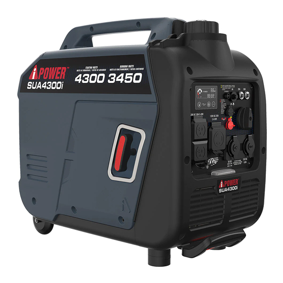
- Page 1 PORTABLE GENERATOR Owner’s Manual SUA4300i DO NOT RETURN TO STORE! CALL US FIRST 855-888-3598 FOR SUPPORT Model# 1492003 REV00 Model: Serial: Date Purchased: SAVE THIS MANUAL FOR FUTURE REFERENCE P/N: 32082-00000-00...
-
Page 2: Table Of Contents
Maintenance And Storage....20 Introduction..........1 Safety............1 Maintenance Schedule......20 General Safety Precautions....2 Engine Maintenance......20 Unpacking the Generator.......7 Engine Oil Level Check......20 Change Engine Oil........21 Parts Included........7 Controls and Features......8 Air Filter Maintenance......22 Control Panel Features......9 Spark Plug Maintenance.......22 Specifications........11 Valve Clearance........22 Cleaning the Spark Arrestor....23 CO WATCH-GUARD......12 Add Engine Oil........14 Generator Maintenance......23... -
Page 3: Introduction
Service at 855-888-3598, or which are known to the State of California to cause www.a-ipower.com for starting, operating and cancer and birth defects orother reproductive harm. servicing procedures. The owner is responsible for To minimize exposure, avoid breathing exhaust, and proper maintenance and safe use of the unit. -
Page 4: General Safety Precautions
Asphyxiation Electric Shock Fire Hazard Hazard Hazard Hot Surface. Explosion Moving Parts Do Not Touch the Surface. Hazard Hazard Burn Hazard Operator’s Manual Kickback GENERAL SAFETY PRECAUTIONS • Operate this product ONLY outside far away from windows, doors and vents to reduce the risk of Using a generator indoors CAN KILL YOU IN MINUTES. - Page 5 CORRECT USAGE Example location to reduce risk of carbon monoxide poisoning • ONLY use outside and downwind, far away from windows, doors and vents. • Direct exhaust away from occupied spaces. INCORRECT USAGE Do not operate in any of the following locations: •...
- Page 6 WARNING NOTICE DO NOT lay the generator on its side when moving, Starter cord kickback (rapid retraction) storing or operating. Oil may leak and damage the will pull hand and arm toward engine engine or your property. faster than you can let go which could cause broken bones, fractures, bruises, WHEN STARTING THE GENERATOR or sprains resulting in serious injury.
- Page 7 • It is a violation of California Public Resource Code, DANGER Section 4442, to use or operate the engine on any Contact with terminals, bare wires and forest-covered, brush-covered, or grass-covered electrical connections when generator land unless the exhaust system is equipped with a is running will result in death or serious spark arrester, as defined in Section 4442, injury.
- Page 8 • DO NOT tamper with governor spring, links or other WARNING parts to increase engine speed. Generator supplies Medical and Life Support Uses. correct rated frequency and voltage when running • In case of emergency, call 911 immediately. at governed speed. •...
-
Page 9: Unpacking The Generator
UNPACKING THE GENERATOR • Open carton completly. Remove and verify carton content prior to assembly. Your generator ships with following items. • Call our customer service at 855-888-3598 with the unit model and serial number for any missing item. • Record model, serial number, and date of purchase on front cover of this munual for your own record. -
Page 10: Controls And Features
CONTROLS AND FEATURES 1 - Recoil Starter 7 - Telescopic Handle 2 - Control Panel 8 - Panel LED Light 3 - Fuel Cap 9 - Support Leg 4 - Maintenance Cover 10 - Muffler/Spark Arrester 5 - Carrying Handle 6 - Wheel Page 08... -
Page 11: Control Panel Features
CONTROL PANEL FEATURES 1. LED DATA CENTER: See LED DATA CENTER section. 6. Starting Dial Switch: Used to start and stop the generator. 2. CO (Carbon Monoxide) WATCH-GUARD Indicator Light (Red for Shut off and Yellow for Service): The 7. 12V DC, Outlet (Automotive): Provides 12 volt DC CO(Carbon Monoxide) WATCH-GUARD monitors for the power up to 8.3 amps. - Page 12 CONTROL PANEL FEATURES LED Data Center 1. LED Multi-Meter: Displays voltage,power,fuel level, 4. Overload Reset Button with Indicator Light: The frequency, and running time. indicator light is green when the inverter is running under rated load. The indicator light will turn to 2.
-
Page 13: Specifications
SPECIFICATIONS SUA4300i Model Number 1492003 Starting Watts 4300W Running Watts 3450W Rated AC Voltage 120V Rated DC Voltage 5V/12V 60HZ Rated Frequency Phase Single Neutral Floating Grounding System (AC) Engine Type Single Cylinder, 4-Stroke OHV Air Cooled Engine Displacement 149cc... -
Page 14: Co Watch-Guard
CO WATCH-GUARD Carbon Monoxide (CO) Detection and Auto Shutoff System Your Generator is equipped with Carbon Monoxide (CO) WATCH-GUARD detect system for your protection and safety. This detecting and shutoff system monitors for the accumulation of poisonous CO gas around the generator produced by engine exhaust when the generator is running. - Page 15 The generator is shutoff automatically and the yellow light will blink for at least five minutes after shutoff. Call A-iPower Customer Service 855-888-3598 for repair. Do not use the generator until the sensor is working properly. The CO WATCH-GUARD must only be serviced by qualified technician to restore it to original settings.
-
Page 16: Add Engine Oil
Add Engine Oil NOTICE We recommend using SAE 10W-30 APISJ oil for We consider the first 5 hours of run time to be the best performance. Other high-quality detergent oils break-in period for the unit. During the break in (APISJ or higher) are acceptable. Do not use special period stay at or below 50% of the running watt additives. -
Page 17: Operation At High Altitude
To operate at high altitudes A-iPower • If fuel spills, wait until it evaporates before starting can provide a high altitude carburetor main jet. The engine. -
Page 18: Operation
OPERATION Generator Location Surge suppressors come in single- or multi-outlet styles. They’re designed to protect against virtually WARNING all short-duration voltage fluctuations. Make sure you review each warning in order to Starting the Generator prevent fire hazard. 1. Before starting the generator, check for loose or missing parts and for any damage which may Using a generator indoors CAN KILL YOU IN MINUTES. -
Page 19: Connecting Electrical Loads
6. Turn the starting dial switch to the RUN 1. Let engine stabilize and warm up for a few minutes position. after starting. 2. Ensure circuit breaker on control panel is in on position. 3. Plug in and turn on the desired 120 Volt AC, single phase, 60Hz electrical loads. -
Page 20: Stopping The Engine
2. Turn the starting dial switch to the OFF 6. Allow the engine to stabilize. position. 7. Repeat steps 5-6 for each additional item. Parallel Operation (2 x SUA4300i Models) WARNING Fire and electrocution hazard. Never connect or WARNING disconnect the parallel cord leads when a generator is running. -
Page 21: Parallel Operation
4. The parallel operation outlets allow you to connect Set up and Operation two AIPOWER generators to increase the total 1. Align the two inverters on a firm, flat and level available electrical power. The AIPOWER Parallel surface at a minimum 20 inch apart. Operation Kit can be purchased. -
Page 22: Maintenance And Storage
MAINTENANCE AND STORAGE MAINTENANCE SCHEDULE NOTE: Maintenance should be performed more frequently Regular Maintenance will improve the performance when generator is used in dusty areas. and extend the life of your generator. Follow When generator has exceeded the maximum figures maintenance schedule intervals whichever occurs specified in the table, maintenance should still be first according to use. -
Page 23: Change Engine Oil
Recommended Engine Oil Type CAUTION 1 0W-3 0 Avoid prolonged or repeated skin contact with used motor oil. 5W-3 0 1 0W-4 0 1. Loosen the bolts and remove the maintenance cover. 5W-3 0 Full Synthetic 2. Remove the oil filler cap. °... -
Page 24: Air Filter Maintenance
6. Measure plug gap. The correct gap is 0.028-0.031 Air Filter Maintenance in. (0.7-0.8 mm). To widen gap, if necessary, 1. Unscrew the bolts carefully bend the ground (top) electrode. To remove the maintenance cover (A). lessen gap, gently tap ground electrode on a hard 2. -
Page 25: Cleaning The Spark Arrestor
Cleaning the Spark Arrestor Short Term Storage Fill the tank with fresh gasoline and add gasoline 1. allow the engine to cool down completely before stabilizer. Drain the carburetor float bowl. carrying out fender maintenance. 1 - Add a properly formulated FUEL STABILIZER to 2. - Page 26 DRAINING THE FLOAT BOWL 1. Turn the fuel tank valve to the OFF position. 2. Locate the drain screw on the bottom of the carburetor float bowl. 3. Place an appropriate gasoline container to catch the drained fuel. 4. Loosen the float bowl drain screw and allow the fuel to drain from the drain tube.
-
Page 27: Trouble Shooting
TROUBLE SHOOTING PROBLEM POSSIBLE CAUSE SOLUTION Engine is running, 1. AC Circuit breaker is open. 1. Check AC load and reset circuit breaker. but no AC output is 2. Fault in generator. 2. Contact customer service or authorized service center. available. -
Page 28: Parts Diagram And Parts List
PARTS DIAGRAM AND PARTS LIST SUA4300i PARTS DIAGRAM Page 26... -
Page 29: Parts List
Parts List Part Number Description Qty. Part Number Description Qty. 30111-00083-00 Philips screw M5*14 33004-01223-00 Engine mounting bracket 30111-00008-00 Philips screw M5*10 30101-00349-00 Hex flange bolt M6*40 30111-00070-00 Philips screw M4*12 34024-00085-00 Clip nut M6 31026-00388-00 Switch knob 33089-00511-00 Base plate 20114-06920-00 Panel assy. -
Page 30: Circuit Diagram
Circuit Diagram Page 28... -
Page 31: Warranty
Warranty Term related service due to obstructions and other build ups resulting from improper maintenance. A-iPower will provide warranty for any of its products Additional exclusions - this warranty does not cover purchased through any authorized AiPower dealer in wearable parts such as filers, spark plugs, o-rings, North America to the original purchaser and will be batteries etc. - Page 32 Warranty limits and Implications and Consequential Damages A-iPower is not obligated to cover any loss of time, use of product, freight cost, or any other incidental or consequential claim from the use of this product. This warranty is in Lieu of all other warranties, express or implied.
- Page 33 Fontana, CA 92337 USA Phone: 855-888-3598 support@a-ipower.com www.a-ipower.com...
- Page 34 A-iPOWER WARRANTY REGISTRATION FORM Register your product by emailing this form to support@a-ipower.com or register on-line at: www.a-ipower.com. Registering your product is important , it provides the following protections: 1. You have record of product purchased 2. Customer Service can Better serve you for Warranty related issues...
- Page 35 Fontana, CA 92337 USA Phone: 855-888-3598 support@a-ipower.com www.a-ipower.com...
Need help?
Do you have a question about the SUA4300i and is the answer not in the manual?
Questions and answers