
Related Manuals for MacDon TM100


Summary of Contents for MacDon TM100
- Page 1 TM100 Tractor Mount Float Module for D1 Series Draper Headers Setup, Operation, and Parts Manual 262150 Revision A Original Instruction The Harvesting Specialists.
- Page 2 © 2022 MacDon Industries, Ltd. The information in this publication is based on the information available and in effect at the time of printing. MacDon Industries, Ltd. makes no representation or warranty of any kind, whether expressed or implied, with respect to the...
- Page 3 Declaration of Conformity 262150 Revision A...
- Page 4 262150 Revision A...
- Page 5 262150 Revision A...
- Page 6 Introduction Your machine The TM100 Tractor Mount Float Module allows a MacDon rigid draper header to be mounted on a conventional farm tractor equipped with a front three-point hitch or rear three-point hitch with reverse drive capability. NOTE: The TM100 is compatible with only 4.6 10.7 m (15 35 ft.) timed double-knife headers.
- Page 7 This manual is available in English, French, and German. These manuals can be ordered from MacDon, downloaded from our Dealer-only site (https://portal.macdon.com) (login required), or downloaded from the MacDon website (www.macdon.com). 262150 Revision A...
-
Page 8: Summary Of Changes
Summary of Changes At MacDon, we re continuously making improvements: occasionally these improvements impact product documentation. The following list provides an account of major changes from the previous version of this document. Section Internal Use Summary of Change Only Declaration of Conformity, Updated the Declaration of Conformity documents. -
Page 9: Serial Number Location
The serial number helps identify your machine and ensures you get the best information quickly when working with MacDon for Product Support or Parts. Record the serial number of the TM100 Tractor Mount Float Module in the space provided. TM100 serial number: __________________________ The serial number plate (A) is located on the rear face of the frame, above the power take-off (PTO) driveline. -
Page 11: Table Of Contents
4.1.2 Connecting Hydraulic Hoses to the Tractor Selective Control Valve Remotes .......... 55 4.1.3 Installing Control Console ......................59 4.1.4 Installing Electrical Harness TM100 to Cab ..................60 4.1.5 Installing Electrical Harness Cab Power..................63 4.2 Attaching Header to Tractor Mount Float Module ..................65 4.3 Running up the Header.......................... - Page 12 TABLE OF CONTENTS 4.4 Detaching Tractor Mount Float Module from Tractor.................. 73 4.5 Detaching Header from Tractor Mount Float Module.................. 77 Chapter 5: Operation..........................81 5.1 Owner/Operator Responsibilities ......................81 5.2 Operational Safety..........................82 5.2.1 Lift Cylinder Safety Props....................... 82 5.2.2 Reel Safety Props .........................
- Page 13 7.10 Selector Valve Assembly ........................140 7.11 Integrated Pump Service Parts ......................142 7.12 Electrical ............................144 7.13 Electrical TM100 to Tractor Cab ......................146 7.14 Hydraulics Multicoupler and Hoses....................148 7.15 TM100 to Three-Point Hitch ....................... 150 7.16 Driveline Power Take-Off to Gearbox Service Parts................152 7.17 TM100 to Header Attaching Parts .....................
-
Page 15: Chapter 1: Safety
Chapter 1: Safety Understanding and consistently following these safety procedures will help to ensure the safety of those operating the machine and of bystanders. 1.1 Safety Alert Symbols The safety alert symbol indicates important safety messages in this manual and on safety signs on the machine. This symbol means: ATTENTION! BECOME ALERT! -
Page 16: Signal Words
SAFETY 1.2 Signal Words Three signal words, DANGER, WARNING, and CAUTION, are used to alert you to hazardous situations. Two signal words, IMPORTANT and NOTE, identify non-safety related information. Signal words are selected using the following guidelines: DANGER Indicates an imminently hazardous situation that, if it is not prevented, will result in death or serious injury. WARNING Indicates a potentially hazardous situation that, if it is not prevented, could result in death or serious injury. -
Page 17: General Safety
SAFETY 1.3 General Safety Operating, servicing, and assembling machinery presents several safety risks. These risks can be reduced or eliminated by following the relevant safety procedures and wearing the appropriate personal protective equipment. CAUTION The following general farm safety precautions should be part of your operating procedure for all types of machinery. - Page 18 SAFETY Wear close-fitting clothing and cover long hair. NEVER wear dangling items such as hoodies, scarves, or bracelets. Keep all shields in place. NEVER alter or remove safety equipment. Ensure that the driveline guards can rotate independently of their shaft, and that they can telescope freely.
-
Page 19: Maintenance Safety
SAFETY 1.4 Maintenance Safety Maintaining your equipment safely requires that you follow the relevant safety procedures and wear the appropriate personal protective equipment for the task. To ensure your safety while maintaining the machine: Review the operator s manual and all safety items before operating or performing maintenance on the machine. - Page 20 SAFETY Wear protective gear when working on the machine. Wear heavy gloves when working on knife components. Figure 1.10: Personal Protective Equipment 262150 Revision A...
-
Page 21: Hydraulic Safety
SAFETY 1.5 Hydraulic Safety Because hydraulic fluid is under extreme pressure, hydraulic fluid leaks can be very dangerous. The proper safety procedures must be followed when inspecting for hydraulic fluid leaks and servicing hydraulic equipment. Always place all hydraulic controls in Neutral before leaving the operator s seat. -
Page 22: Welding Precaution
SAFETY 1.6 Welding Precaution Welding should never be attempted on the header while it is connected to the tractor. WARNING Severe damage to sensitive, expensive electronics can result from welding on the header while it is connected to the tractor. It can be impossible to know what effect high current could have with regard to future malfunctions or shorter lifespan. -
Page 23: Safety Signs
SAFETY 1.7 Safety Signs Safety signs are decals placed on the machine where there is a risk of personal injury, or where the Operator should take extra precautions before operating the controls. They are usually yellow. Keep safety signs clean and legible at all times. Replace safety signs that are missing or illegible. -
Page 24: Safety Decal Locations
Safety signs are usually yellow decals, and are placed on the machine where there is a risk of personal injury, or where the operator has to take extra precaution before operating controls. Figure 1.15: TM100 Safety Decal Locations A - MD #313728 – Hot Fluid Spray Hazard, Read Operator’s Manual B - MD #166832 –... -
Page 25: Understanding Safety Signs
SAFETY 1.9 Understanding Safety Signs Safety sign decals use illustrations to convey important safety or equipment maintenance information. MD #158289 Driveline entanglement hazard DANGER A rotating driveline contact can cause death keep away! Do NOT operate without: All driveline guards and equipment shield in place. Driveline guards that turn freely on the driveline. - Page 26 SAFETY MD #171287 Crushing hazard DANGER To prevent injury or death from the fall of a raised pull-type: Fully raise the pull-type, stop the engine, remove the key, and engage the hydraulic safety lock before going under the pull-type. Alternatively, rest the pull-type on the ground, stop the engine, and remove the key before servicing the machine.
- Page 27 SAFETY MD #313728 General hazard pertaining to machine operation and servicing / Hot fluid spray hazard DANGER To prevent injury or death from improper or unsafe machine operation: Read the operator s manual and follow all safety instructions. If you do not have a manual, obtain one from your Dealer.
-
Page 29: Chapter 2: Product Overview
Chapter 2: Product Overview In this chapter, terms used in this manual are defined and basic information about the machine is provided including product specifications and images of the main machine components. 2.1 Definitions The following terms, abbreviations, and acronyms are used in this manual. Table 2.1 Definitions Term Definition... - Page 30 PRODUCT OVERVIEW Table 2.1 Definitions (continued) Term Definition A tightening procedure in which a fitting is assembled to a specified tightness (usually Torque angle finger tight) and then the nut is turned farther by a specified number of degrees until it achieves its final position The relationship between the assembly torque applied to a piece of hardware and the Torque-tension...
-
Page 31: Specifications
PRODUCT OVERVIEW 2.2 Specifications Specifications and design are subject to change without notice or obligation to revise previously sold units. Table 2.2 Specifications TM100 Front Mount Float Module Three-point hitch compatibility Category 2/3/3N Header compatibility D115, D120, D125, D130, and D135 double knife 1186 mm (47 in.) -
Page 32: Dimensions
PRODUCT OVERVIEW 2.3 Dimensions When transporting or operating a TM100, it is important to know the dimensions of the machine. Figure 2.1: TM100 Dimensions A - 2991 mm (118 in.) B - 1306 mm (51 in.) C - 1186 mm (47 in.) -
Page 33: Component Identification
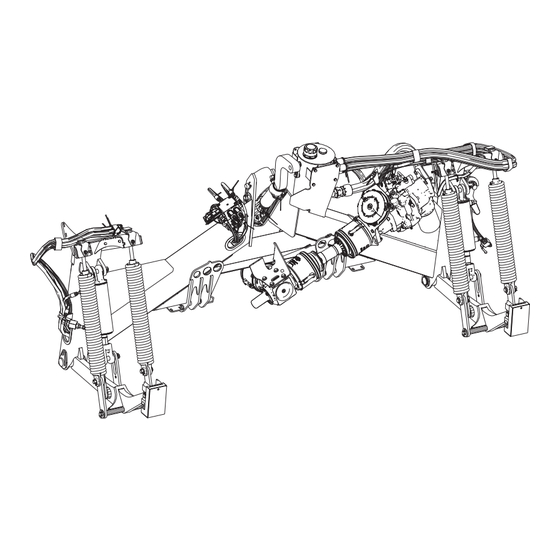
2.4 Component Identification Operating and maintaining the machine is easier if you are familiar with the location of the float module s main components. Figure 2.2: Header Side of TM100 A - Float Springs (2 Per Side) B - Lift Cylinder, Slave... - Page 34 PRODUCT OVERVIEW Figure 2.3: Tractor Side of TM100 A - Cooling Fan B - Header Tilt Cylinder C - Hydraulic Reservoir E - PTO Driveline 2 D - Float Links (2 per side) F - Tractor Pick-Up, Categories 2/3N/3 G - PTO Driveline Holder (Shown in Storage Position) Three options: 1 3/8 in.
-
Page 35: Chapter 3: Unloading And Assembling Tractor Mount Float Module
Chapter 3: Unloading and Assembling Tractor Mount Float Module Unload and unpack all TM100 parts before beginning assembly. Carefully follow these procedures in the order in which they are presented. 3.1 Unloading Tractor Mount Float Module Familiarize yourself with the procedure and prepare the equipment necessary to remove the TM100 from the shipping container. - Page 36 UNLOADING AND ASSEMBLING TRACTOR MOUNT FLOAT MODULE 1. Move the trailer into position and block the wheels. 2. Lower the trailer storage stands. 3. Open the container doors and remove the materials that brace the load. 4. Check the container floor. Remove nails and other obstructions if necessary. 5.
-
Page 37: Moving Tractor Mount Float Module To Assembly Area
UNLOADING AND ASSEMBLING TRACTOR MOUNT FLOAT MODULE 3.2 Moving Tractor Mount Float Module to Assembly Area Safely move the TM100 to an area to complete assembly and attach to the tractor. DANGER The equipment used for loading or unloading a float module must meet or exceed the requirements specified in this document. -
Page 38: Unpacking The Tractor Mount Float Module
3.3 Unpacking the Tractor Mount Float Module Shipping wires and packaging must be removed in order to complete the assembly of the TM100. 1. Cut the shipping wire and remove the parts bags from the shipping position on each lift cylinder at the front of the TM100. - Page 39 Four M20 x 30 mm hex bolts (D) (MD #252891) Eight hardened washers (E) (MD #21540) Four flat washers (F) (MD #18601) Figure 3.8: Parts in Lift Arm Locking Brackets and Hardware Bag Electrical and Hydraulic Connections Bag Harness TM100 to header (A) (MD #333181) 262150 Revision A...
- Page 40 Multicoupler with fittings (C) (MD #333422) Four #8 ORB fittings (D) (MD #135563) Suction cup base (E) (MD #287859) Harness TM100 power (F) (MD #333266) Harness TM100 power (G) (MD #333265) Harness TM100 to cab (H) (MD #333569) 262150 Revision A...
- Page 41 UNLOADING AND ASSEMBLING TRACTOR MOUNT FLOAT MODULE Figure 3.9: Parts in Electrical and Hydraulic Connections Bag 262150 Revision A...
- Page 42 UNLOADING AND ASSEMBLING TRACTOR MOUNT FLOAT MODULE Hydraulic Hoses Bag Four 9000 mm hoses (A) (MD #333420) Figure 3.10: Parts in Hydraulic Hoses Bag 262150 Revision A...
-
Page 43: Removing Shipping Stands
Two inboard shipping channels (B) should be removed prior to attaching the TM100 to the tractor. Two outboard shipping channels (C) can be removed after the TM100 is attached to the tractor. If attached to a tractor, raise the tractor s three- point linkage sufficiently to remove the shipping channels located under the TM100 lift arms. - Page 44 Figure 3.14: Shipping Channel – Left Side Lower the TM100 to the ground. If chains were used, remove the chains from lift lugs (B). Remove two M12 bolts (A) and nuts, and remove lift lug (B).
- Page 45 Remove shipping wire and wood block (A) that secure rubber block (B) in place. Repeat this step on the opposite lift arm. NOTE: To attach the TM100 to a header, rubber block (B) must pivot freely. Figure 3.16: Lift Arm – Right Side...
-
Page 46: Installing Hose Guide
A new hose guide (MD #333378) is provided that replaces the existing hose guide on the left side of the header. The existing hose guide on the header is reused for the hoses on the right side of the TM100. - Page 47 UNLOADING AND ASSEMBLING TRACTOR MOUNT FLOAT MODULE 2. Install hose guide (A) removed from the header onto the right side of the TM100 using two M10 x 30 mm carriage bolts (MD #184662) and center lock flange nuts (MD #135799) (B).
-
Page 48: Installing Power Take-Off Driveline
To install the PTO driveline onto the float module, follow these steps: 1. Identify which end of the driveline attaches to the TM100 gearbox. The end with taper pin (A) attaches to the gearbox, and the end with quick-disconnect collar (B) attaches to the tractor PTO. - Page 49 UNLOADING AND ASSEMBLING TRACTOR MOUNT FLOAT MODULE 2. Remove lock nut (A) and washer (B), and tap out pin (C). Figure 3.23: Retaining Pin – Gearbox End 3. Unlatch driveline cover (A) from the gearbox. Figure 3.24: Driveline Cover 4. Slide the cover over the driveline. Align the splines on driveline yoke (A) with gearbox shaft (B), and slide the yoke onto the shaft.
- Page 50 Figure 3.28: Driveline Cover If putting the PTO driveline into storage position, proceed as follows: NOTE: The TM100 must be detached from the tractor before moving the storage bracket into the storage position. 262150 Revision A...
- Page 51 UNLOADING AND ASSEMBLING TRACTOR MOUNT FLOAT MODULE 9. Remove pin (A) securing storage bracket (C) to the float module frame. IMPORTANT: Keep lower pin (B) installed because it secures the center- link to the frame. Remove only the lynch pin and washer to access the storage bracket.
- Page 52 UNLOADING AND ASSEMBLING TRACTOR MOUNT FLOAT MODULE 13. Remove hair pin (A), and slide out hitch pin (B) enough to allow room to install the storage bracket at location (C). Figure 3.32: Three-Point Hitch Pin 14. Secure storage bracket (B) to the frame using three-point linkage pin (A).
-
Page 53: Confirming Correct Gearbox Rotation
You may need to remove cone shield (E) attached to the pump to be able so see the rotation. IMPORTANT: Incorrect gearbox rotation will damage drive pump (D). 3. If the pump input shaft is rotating in the wrong direction, the TM100 gearbox needs to be rotated 180°. For instructions, refer to 3.8 Repositioning Gearbox, page Figure 3.35: Correct Gearbox Rotation... -
Page 54: Repositioning Gearbox
UNLOADING AND ASSEMBLING TRACTOR MOUNT FLOAT MODULE 3.8 Repositioning Gearbox The TM100 gearbox is factory-set for counterclockwise power take-off (PTO) rotation. If the tractor has clockwise PTO rotation, the TM100 gearbox needs to be rotated 180°. To reposition the gearbox, follow these steps: 1. - Page 55 UNLOADING AND ASSEMBLING TRACTOR MOUNT FLOAT MODULE 6. Note the orientation of both back plates (A) and (B). After repositioning the gearbox, the back plates need to be installed in their original orientation to minimize the chain length hanging below the gearbox. Figure 3.39: Back Plates 7.
- Page 56 UNLOADING AND ASSEMBLING TRACTOR MOUNT FLOAT MODULE 9. Set the gearbox onto the ground upside down to prevent oil spillage when removing breather (A). IMPORTANT: Breather (A) must be facing up when the gearbox is installed. 10. Remove four bolts (B) securing plate (C) to the rear of the gearbox.
- Page 57 UNLOADING AND ASSEMBLING TRACTOR MOUNT FLOAT MODULE 13. Reinstall the back plate to the rear of the gearbox using retained bolts (B). Ensure tab (A) where the chain attaches is positioned as shown. Apply medium strength threadlocker (Loctite ® 243 or equivalent) to the bolt threads and tighten the bolts to 20 Nm (15 lbf·ft).
- Page 58 UNLOADING AND ASSEMBLING TRACTOR MOUNT FLOAT MODULE 15. Apply medium-strength threadlocker (Loctite 243 ® equivalent) on bolts (A). 16. Install gearbox shaft cover (C) and shield clamp plate (B) using retained bolts (A) and washers. Tighten the bolts to 17 Nm (12.5 lbf·ft). Figure 3.47: Gearbox Shaft Cover 17.
- Page 59 After tightening, the pin MUST be recessed into the yoke 2 4 mm, otherwise driveline and gearbox damage may occur. Figure 3.51: Taper Pin 23. Latch driveline shield (A) back onto back plate (B) on the gearbox. Figure 3.52: TM100 Driveline Cover 262150 Revision A...
-
Page 61: Chapter 4: Attaching And Detaching Tractor Mount Float Module
Chapter 4: Attaching and Detaching Tractor Mount Float Module This chapter includes instructions for attaching and detaching the TM100 to and from the tractor and header. 4.1 Attaching Tractor Mount Float Module to a Tractor The TM100 allows attachment of D1 Series Draper Headers to three-point hitch categories 2, 3N, and 3. - Page 62 B - 400 mm (15 3/4 in.) 3. Confirm the power take-off (PTO) s direction of rotation as indicated by arrow (A) near the PTO shaft. The TM100 gearbox is factory-set for counterclockwise PTO rotation. If the tractor has clockwise PTO rotation, rotate the TM100 gearbox 180°.
- Page 63 ATTACHING AND DETACHING TRACTOR MOUNT FLOAT MODULE 4. Remove PTO driveline (A) and storage bracket (B) from the storage position. Figure 4.4: PTO Driveline in Storage Position 5. Secure storage bracket (C) to the float module frame as shown using existing pin (A). IMPORTANT: Do NOT remove lower pin (B) because it secures the center- link to the frame.
- Page 64 ATTACHING AND DETACHING TRACTOR MOUNT FLOAT MODULE 6. Clean and grease tractor PTO and implement shaft before installing the driveline. 7. Pull back collar (B) on the driveline, and slide the driveline onto tractor s PTO shaft (A) until it locks in place. Release the collar and ensure the yoke is locked onto the shaft.
-
Page 65: Shortening The Power Take-Off Driveline
ATTACHING AND DETACHING TRACTOR MOUNT FLOAT MODULE 4.1.1 Shortening the Power Take-Off Driveline It may be necessary to shorten the power take-off (PTO) driveline so that it does not bottom out when the three-point linkage is fully raised and to ensure that there is enough room to remove the driveline s quick disconnect from the tractor PTO shaft. - Page 66 ATTACHING AND DETACHING TRACTOR MOUNT FLOAT MODULE 8. Remove driveline (A) from the tractor s PTO shaft. 9. Remove three Phillips head screws (A) from the shielding. Figure 4.12: Removing Shielding 10. Remove shield tube (A) from driveline shaft (B). Figure 4.13: Removing Shielding 11.
- Page 67 ATTACHING AND DETACHING TRACTOR MOUNT FLOAT MODULE 12. Secure the driveline shaft in a vise. Using measurement (L) taken in Step 7, page 51, mark shaft (A) and cut to the required length. IMPORTANT: Carefully file away burrs from the end of the tube, and remove all filings.
- Page 68 16. Grease the internal drive tube and reattach outer cone (A) and shield tube (B) using three screws (C). Figure 4.19: Installing Shielding 17. Remove the other driveline half from the TM100 gearbox as follows: Remove nut (C) and washer (B).
-
Page 69: Connecting Hydraulic Hoses To The Tractor Selective Control Valve Remotes
Figure 4.22: Tractor PTO 4.1.2 Connecting Hydraulic Hoses to the Tractor Selective Control Valve Remotes Hydraulic hoses are used to connect the TM100 to the selective control valve (SCV) on the tractor. 1. Locate pressure and return hoses (A) on the selector valve:... - Page 70 Figure 4.24: Tractor Front SCV 4. Locate the eight hydraulic hoses four 9000 mm (30 ft.) (A) and four 3000 mm (10 ft.) (B) provided with the TM100. Four of the eight hoses are required. Choose the correct hose length for each connection depending on which end of the tractor the SCV is located.
- Page 71 ATTACHING AND DETACHING TRACTOR MOUNT FLOAT MODULE 6. If routing hoses (A) from a front SCV, secure the hoses using strap (B) on the hydraulic tank. Figure 4.27: Front SCV Hose Routing 7. For hoses routed from the rear SCV, route hoses (A) to the front of the tractor, along the left side of the three-point hitch toward the multicoupler receptacle.
- Page 72 13. Position multicoupler (A) onto the receptacle and push the handle to engage the multicoupler pins into the receptacle. 14. Push the handle to the closed position until the lock button snaps out. Figure 4.31: Multicoupler Connected to TM100 262150 Revision A...
-
Page 73: Installing Control Console
The control console allows for in-cab control of header functions such as draper speed, deck shift, reel position, and header tilt. Control console (A) and suction cup base (B) are provided with the TM100. Figure 4.32: Control Console and Base 1. Attach suction cup base (B) to ball mount (A) on the back of the control console. -
Page 74: Installing Electrical Harness Tm100 To Cab
ATTACHING AND DETACHING TRACTOR MOUNT FLOAT MODULE 4.1.4 Installing Electrical Harness – TM100 to Cab Electrical harness MD #333569 connects the TM100 to the tractor cab. Figure 4.35: Harness MD #333569 A - C20A-TM – Connects to TM100 B - C84A-TM – Connects to Control Box in Cab C - C83B-TM –... - Page 75 ATTACHING AND DETACHING TRACTOR MOUNT FLOAT MODULE 3. Starting at the TM100, route harness (A) along the left side of three-point hitch (B) and under the left side of the cab. IMPORTANT: When routing the harness, avoid pinch points on the tractor, and avoid hot surfaces that could damage the harness.
- Page 76 ATTACHING AND DETACHING TRACTOR MOUNT FLOAT MODULE 6. Route harness (A) around the rear of the cab, and then inside the cab toward the console. Figure 4.39: Routing Harness – Rear of Tractor Figure 4.40: Routing Harness into Cab 7. Connect 12-pin connector C84A-TM (A) to the bottom of control box (B).
-
Page 77: Installing Electrical Harness Cab Power
Figure 4.43: Connectors C471B-TM and C471A-TM 4.1.5 Installing Electrical Harness – Cab Power An electrical harness must be installed to connect the TM100 to the tractor s power supply. Two electrical harness options are provided: MD #333265 (A) Terminated with flying leads (C). These can be spliced/connected to whatever the cab has for a power outlet, such as a circular cigarette lighter power plug. - Page 78 The tractor end of the circuit must be capable of handling the 25 amp draw requirement and must be fused for 25 amps. 2. Connect C83A-TM (A) to plug C83B-TM (B) on TM100 harness (MD #333569). Figure 4.45: Connecting Cab Power Harness to TM100 Harness A - C83A-TM –...
-
Page 79: Attaching Header To Tractor Mount Float Module
ATTACHING AND DETACHING TRACTOR MOUNT FLOAT MODULE 4.2 Attaching Header to Tractor Mount Float Module Follow this procedure to ensure the header is attached correctly to the TM100. DANGER To prevent bodily injury or death from the unexpected start-up or fall of a raised machine, always stop the engine and remove the key before leaving the operator’s seat, and always engage the safety props before going under the... - Page 80 Secure locking bracket using pin (C), two flat washers (D) (one per side), and two retaining rings (E) (one per side). The locking bracket and hardware are provided with the TM100. Figure 4.48: Lift Arm Locking Bracket 4. Remove header stand (A) from the header leg.
- Page 81 ATTACHING AND DETACHING TRACTOR MOUNT FLOAT MODULE 7. Start the engine, and lower the three-point linkage as needed so lift arms (A) are aligned with header legs (B). 8. While maintaining alignment between lift arms (A) and header legs (B), drive slowly forward until lift arms (A) contact stops (C) in the header legs.
- Page 82 Retract lift cylinders (A) and hold the SCV control as necessary until both cylinders reach equal retracted length. NOTE: This procedure allows the cylinders to rephrase to ensure even lift in operation. Figure 4.55: TM100 Lift Cylinder 262150 Revision A...
- Page 83 The lift cylinders are locked when handle (A) is oriented 90 degrees to valve (B) and the hydraulic lines. Figure 4.56: TM100 Lift Cylinder Lockout Valve – Left Side 19. On the right side of the float module, route hose bundle (A) over hose support (B).
- Page 84 Figure 4.60: Harness MD #333181 29. Unlock both lift cylinders. The lift cylinders are unlocked when handle (A) is parallel with valve (B). 30. Lower the header to the ground. Figure 4.61: TM100 Lift Cylinder Lockout Valve – Left Side 262150 Revision A...
- Page 85 ATTACHING AND DETACHING TRACTOR MOUNT FLOAT MODULE 31. Set the header float as follows: NOTE: The recommended float setting for cutting on the ground is when there is approximately 34 kg (75 lb.) weight on each side of the header at the cutterbar. Readjust as needed for the given field conditions.
-
Page 86: Running Up The Header
ATTACHING AND DETACHING TRACTOR MOUNT FLOAT MODULE 4.3 Running up the Header Operate the header and check for any problems. DANGER Ensure that all bystanders have cleared the area. 1. Start the tractor and engage the power take-off (PTO). 2. Raise and lower the reel to ensure the hoses are properly connected. 3. -
Page 87: Detaching Tractor Mount Float Module From Tractor
ATTACHING AND DETACHING TRACTOR MOUNT FLOAT MODULE 4.4 Detaching Tractor Mount Float Module from Tractor To detach the TM100 from the tractor, follow the recommended procedure provided here. DANGER To prevent bodily injury or death from the unexpected start-up or fall of a raised machine, always stop the engine, remove the key, and engage the safety props before going under the header for any reason. - Page 88 8. Store the multicoupler and hoses with the tractor. Figure 4.66: Multicoupler Connected to TM100 9. Detach the three-point linkage from the float module. Ensure all pins (A) are replaced and secured on the float module frame.
- Page 89 ATTACHING AND DETACHING TRACTOR MOUNT FLOAT MODULE 12. Remove pin (A) securing storage bracket (C) to the float module frame. IMPORTANT: Keep lower pin (B) installed because it secures the center- link to the frame. Remove only the lynch pin and washer to access the storage bracket.
- Page 90 ATTACHING AND DETACHING TRACTOR MOUNT FLOAT MODULE 16. Remove hair pin (A), and slide out three-point hitch pin (B) enough to allow room to install the storage bracket at location (C). Figure 4.72: Three-Point Hitch Pin 17. Secure storage bracket (B) to the frame using three-point linkage pin (A).
-
Page 91: Detaching Header From Tractor Mount Float Module
ATTACHING AND DETACHING TRACTOR MOUNT FLOAT MODULE 4.5 Detaching Header from Tractor Mount Float Module To detach the TM100 from the header, follow the recommended procedure provided here. Keep the float module attached to the header during transport. Detach the float module only if performing the... - Page 92 7. Engage both safety props on the float module lift cylinders. The lift cylinders are locked when handle (A) is oriented 90 degrees to valve (B) and the hydraulic lines. Figure 4.77: TM100 Lift Cylinder Lockout Valve – Left Side 8. Remove bolts (B) and washers (C) securing locking bracket (A).
- Page 93 ATTACHING AND DETACHING TRACTOR MOUNT FLOAT MODULE 9. Remove lynch pin and clevis pin (A), and disconnect center- link (B). Reinstall pins (A). CAUTION Center-link (B) is very heavy. The end of the rod is solid steel. Figure 4.79: Center-Link 10.
- Page 94 ATTACHING AND DETACHING TRACTOR MOUNT FLOAT MODULE 13. At the right side of the float module, disconnect reel drive and reel position hoses (A) from header hoses (C). 14. Remove the hoses from support (B), and store the hoses on the float module.
-
Page 95: Chapter 5: Operation
• It is your responsibility to read and understand this manual completely before operating the header. Contact your MacDon Dealer if an instruction is not clear to you. • Follow all safety messages in the manual and on safety decals on the machine. -
Page 96: Operational Safety
• Operate only in daylight or good artificial light. 5.2.1 Lift Cylinder Safety Props The TM100 safety props prevent the lift cylinders from unexpectedly retracting and lowering the header. DANGER To prevent bodily injury or death from the unexpected start-up or fall of a raised machine, always stop the engine, remove the key, and engage the safety props before going under the header for any reason. -
Page 97: Reel Safety Props
OPERATION 1. To engage the TM100 safety props, turn handle (A) so it is oriented 90° to valve (B) and the hydraulic lines. Repeat this step on the opposite lift arm. Figure 5.2: TM100 Lift Cylinder Lockout Valve – Left Side 2. - Page 98 OPERATION 1. Raise the reel fully. 2. Shut down the engine, and remove the key from the ignition. 3. Move reel safety props (A) to the engaged position as shown in Figure 5.4, page 84. The prop MUST be placed on the top surface of raised lug (B), making contact with the cylinder mount, to ensure positive engagement.
-
Page 99: Disengaging Reel Safety Props
OPERATION Disengaging Reel Safety Props Disengage the reel safety props once you have completed working on or around a raised reel. DANGER To prevent bodily injury or death from the unexpected start-up of the machine, always stop the engine and remove the key from the ignition before making adjustments to the machine. -
Page 100: Daily Start-Up Check
OPERATION 5.2.3 Daily Start-Up Check Perform these checks daily before attempting to operate the machine. CAUTION • Clear the area of bystanders. Keep children away from machinery. Walk around the machine to be sure no one is under, on, or close to it. •... -
Page 101: Break-In Period
OPERATION 5.3 Break-in Period A brand-new machine must be operated gently when it is run for the first time. CAUTION Before investigating an unusual sound or attempting to correct a problem, shut off the engine and remove the key from the ignition. -
Page 102: Shutting Down Tractor
OPERATION 5.4 Shutting down Tractor Before leaving the operator s seat for any reason, shut down the tractor. DANGER To prevent bodily injury or death from the unexpected start-up of the machine, always stop the engine and remove the key from the ignition before leaving the operator’s seat for any reason. To shut down the tractor, follow these steps: 1. -
Page 103: Cab Controls
Run the reel at a speed that allows consistent feeding without excessive header vibration. Reduce ground speed if necessary to reduce reel speed. The following controls are available on the control console supplied with the TM100: Draper speed Deck position (if equipped with hydraulic deck shift) - Page 104 Reel height/fore-aft and header angle controls operate using common SCV controls. Use the in-cab control console to switch between these functions. Figure 5.9: TM100 In-Cab Control Box Table 5.1 TM100 In-Cab Control Box Functions A Draper speed Rotate knob (A) to the desired draper speed setting. Position 6 is for normal crop delivery.
-
Page 105: Header Float
OPERATION 5.6 Header Float The header float system reduces the ground pressure at the cutterbar, allowing the header to more easily follow the ground and quickly respond to sudden ground contour changes or obstacles. D1 Series draper headers perform best with minimum ground pressure under normal conditions. Readjust the float if adding/removing optional attachments to the header that affect header weight. - Page 106 OPERATION 1. Loosen bolts (B) and rotate spring locks (C) out of the way. 2. Adjust the header float as follows: IMPORTANT: Turn each bolt pair equally. To increase float (decrease header weight), turn both adjustment bolts (A) clockwise. Repeat the adjustment at the opposite side of the float module.
-
Page 107: Windrow Types
OPERATION 5.7 Windrow Types Review the qualities that make up a good windrow to better understand how the crop delivery method affects your windrow. There are three basic criteria by which the quality of a windrow is measured: Weight Distribution: Heads and stalks distributed evenly across full width of windrow Good Curing: A loose, open windrow for better drying Good Weatherability: A well-formed windrow that supports heads off the ground and holds together in extreme weather conditions... - Page 108 OPERATION Table 5.2 Windrow Descriptions (continued) Windrow Type Windrow Descriptions Description: The stalks are lined along outside edges of windrow and heads are crossed in Dovetail center. This windrow can be formed by center delivery only. Weight Distribution: Poor Curing: Fair Weatherability: Poor Machine Setting Guidelines: High draper speed...
- Page 109 OPERATION Table 5.2 Windrow Descriptions (continued) Windrow Type Windrow Descriptions Description: The stalks are lined along one edge and heads are along opposite edge, 45° to 45° Diagonal windrow perpendicular. This windrow can be formed by end delivery or by center delivery, if the crop is leaning to one side.
-
Page 110: Haying Tips
OPERATION 5.8 Haying Tips These tips may be useful when using the header in hay crops 5.8.1 Curing Curing crops quickly helps maintain the highest quality because for each day that hay lies on the ground, 5% of the protein is lost. -
Page 111: Windrow Characteristics
OPERATION 5.8.4 Windrow Characteristics Adjust speed and header variables to achieve the ideal windrow characteristics. Table 5.3 Windrow Characteristics Configuration Advantage Movement of air through the windrow is more important to the curing High and fluffy process than is direct sunlight. Permits an even flow of material into the baler, chopper, etc. -
Page 113: Chapter 6: Maintenance And Servicing
Chapter 6: Maintenance and Servicing The following instructions provide information about routine service. Log hours of operation and use the maintenance record provided (refer to 6.2.1 Maintenance Schedule/Record, page 100) to keep track of your scheduled maintenance. 6.1 Preparing Machine for Servicing Observe all safety precautions before beginning service on the machine. -
Page 114: Maintenance Requirements
MAINTENANCE AND SERVICING 6.2 Maintenance Requirements Regular maintenance is the best insurance against early wear and untimely breakdowns. Following the maintenance schedule will increase your machine s life. Periodic maintenance requirements are organized according to service intervals. When servicing the machine, refer to the appropriate section in this chapter and use only the fluids and lubricants specified in Recommended Fluids and Lubricants on the inside back cover. -
Page 115: Break-In Inspection
MAINTENANCE AND SERVICING ▲ Hydraulic oil filter 500 Hours or 2 Years (Whichever Occurs First) ▲ Gearbox lubricant ▲ Hydraulic oil 6.2.2 Break-In Inspection Break-in inspections involve checking belts, fluids, and performing general machine inspections for loose hardware or other areas of concern. - Page 116 MAINTENANCE AND SERVICING Use a piece of cardboard or paper to search for leaks. IMPORTANT: Keep hydraulic coupler tips and connectors clean. The introduction of dust, dirt, water, or foreign material into a hydraulic system is the major cause of damage. Do NOT attempt to service hydraulic systems in the field.
-
Page 117: Lubrication And Servicing
MAINTENANCE AND SERVICING 6.3 Lubrication and Servicing Greasing points are marked on the machine by decals showing a grease gun and the grease interval in hours of operation. CAUTION To avoid personal injury, before servicing header or opening drive covers, follow procedures in 6.1 Preparing Machine for Servicing, page Refer to the inside back cover for recommended lubricants. - Page 118 Change hydraulic oil filter (A). For instructions, refer to 6.4.4 Changing Oil Filter, page 110. Figure 6.5: TM100 Oil Filter Every 50 hours Apply grease every 50 hours of operation to the grease points shown in Figure 6.6, page 105.
- Page 119 MAINTENANCE AND SERVICING Figure 6.6: Grease Points – Every 50 Hours A - Lift Arm Pivot (x2) B - Lift Arm Pivot (x2) C - PTO Driveline Universal (x2) D - PTO Driveline Slip Joint E - PTO Driveline Guard (x2) F - Driveline Universal (x2) G - Driveline Slip Joint H - Driveline Guard (x2)
- Page 120 Every 250 hours Change hydraulic oil filter (A). For instructions, refer to 6.4.4 Changing Oil Filter, page 110. Figure 6.8: TM100 Oil Filter Every 500 hours Change the gearbox oil. For instructions, refer to 6.5.2 Changing Oil in Header Drive Gearbox, page 112.
-
Page 121: Lubricating The Tractor Mount Float Module
MAINTENANCE AND SERVICING Every 500 hours Change the hydraulic oil. For instructions, refer to 6.4.3 Changing Oil in Hydraulic Reservoir, page 110. Figure 6.10: Hydraulic Reservoir A - Drain plug B - Filler cap 6.3.2 Lubricating the Tractor Mount Float Module Greasing points are marked on machine by decals showing a grease gun and grease interval in hours of operation. - Page 122 3. Leave excess grease on the fitting to keep out dirt. 4. Replace any loose or broken fittings immediately. Figure 6.12: TM100 Grease Point Decal 5. Remove and thoroughly clean any fitting that will not take grease. Also clean the lubricant passageway. Replace fittings if necessary.
-
Page 123: Hydraulics
MAINTENANCE AND SERVICING 6.4 Hydraulics The TM100 Tractor Mount Float Module s hydraulic system drives the header drapers and knife drives. The tractor s hydraulic system drives the reel hydraulics and header tilt. The oil reservoir is located at the center of the float module frame. Refer to the inside back cover for oil requirements. -
Page 124: Changing Oil In Hydraulic Reservoir
MAINTENANCE AND SERVICING 4. Clean any dirt or debris from filler cap (A). 5. Loosen and remove filler cap (A) by turning it counterclockwise. 6. Add warm oil (approximately 21°C [70°F]) and fill to the required level. Refer to the inside back cover for oil type and specification. - Page 125 IMPORTANT: Do NOT use a filter wrench to install the new filter. Figure 6.16: TM100 Oil Filter Overtightening can damage the O-ring and filter. 5. Turn the new filter into the pump until the O-ring contacts the mating surface. Hand-tighten the filter an additional 1/2 to 3/4 turn.
-
Page 126: Header Drive
MAINTENANCE AND SERVICING 6.5 Header Drive 6.5.1 Checking Oil Level in Header Drive Gearbox Check the header drive gearbox oil level every 100 hours. DANGER To prevent injury or death from the unexpected start-up of the machine, always stop the engine and remove the key from the ignition before leaving the operator’s seat for any reason. - Page 127 MAINTENANCE AND SERVICING 3. Raise or lower the header to position oil drain plug (A) at its lowest point. 4. Disengage the PTO, shut down the engine, and remove the key from the ignition. 5. Place a suitably sized container (approximately 2 liters [0.5 US gal]) underneath the gearbox drain to collect the oil.
- Page 128 MAINTENANCE AND SERVICING 9. Add oil through level plug hole (B) until oil level is up to the bottom of the hole. Use SAE 85W-140 gear lubricant. NOTE: The header drive gearbox holds approximately 0.8 liters (0.83 quarts) of oil. 10.
-
Page 129: Selector Valve Manifold
MAINTENANCE AND SERVICING 6.6 Selector Valve Manifold The selector valve manifold enables the tractor to share one hydraulic circuit between three header functions: header tilt, reel height, and reel fore-aft. The Operator can switch between these three functions using the provided cab control console. -
Page 130: Selector Valve Manifold Hydraulic Connections
MAINTENANCE AND SERVICING 6.6.2 Selector Valve Manifold – Hydraulic Connections In order to aid with the service or repair of the selector manifold, this topic describes the hydraulic ports and their functions. Figure 6.22: Selector Valve Manifold Hydraulic Connections Table 6.3 Selector Valve Manifold Hydraulic Connections Ref. -
Page 131: Integrated Pump
MAINTENANCE AND SERVICING 6.7 Integrated Pump The knife and side draper drives are powered by a hydraulic pump. The required relief and flow settings are integrated within the pump. Figure 6.23: Integrated Pump (MD #333086) A - Knife Drive B - Side Draper Drive 262150 Revision A... - Page 132 MAINTENANCE AND SERVICING Figure 6.24: Integrated Pump (MD #333086) A - Port SDP B - Port KP C - Port T D - Port KR E - Port SDR F - Port D G - Port KS H - Filter J - Flow Control Valve K - Knife Drive Pressure Compensator L - Draper Flow and Pressure Compensator...
-
Page 133: Chapter 7: Repair Parts
Chapter 7: Repair Parts This chapter lists all the replacement parts that can be ordered for a TM100 Tractor Mount Float Module. 7.1 Abbreviations A/R as required (quantity varies) ASSY assembly BHRN button head rib neck BV ball valve CCW counterclockwise... -
Page 134: Serial Number Breaks
REPAIR PARTS 7.2 Serial Number Breaks The side of the serial number on which the dash ( ) appears determines whether the part is used "up to" or "after" the serial number given. Example: 451189 Used on machines up to and including serial number 451189 451190 Used on machines including and after serial number 451190 262150 Revision A... -
Page 136: Lift Arms And Center-Link
7.3 Lift Arms and Center-Link 262150 Revision A... - Page 137 REPAIR PARTS Part Description Number Serial Number 333425 CYLINDER LIFT, MASTER 333361 SEAL KIT 333426 CYLINDER LIFT, SLAVE 333362 SEAL KIT 333336 CYLINDER TOP LINK 123978 SEAL KIT 333494 CLEVIS WELDMENT 333490 LINK TILT, MACHINED 135995 PIN CLEVIS 18609 PIN COTTER 1/4 DIA X 2 ZP 333538 KIT LIFT ARM 327600...
-
Page 138: Float Springs
7.4 Float Springs 262150 Revision A... - Page 139 REPAIR PARTS Part Description Number Serial Number PLATE – SPRING LOCKS 333081 333484 ARM LINK 304034 SPRING ASSEMBLY 30463 PIN CLEVIS 18609 PIN COTTER 1/4 DIA X 2 ZP 18608 PIN COTTER 3/16 DIA X 1.5 ZP 136088 BOLT HEX HD TFL M20 X 2.5 X 450 X SPCL-8.8-AA1J 136506 BOLT RHSSN M10 X 1.5 X 25-8.8-AA1J 135799...
-
Page 140: Header Drive
7.5 Header Drive 262150 Revision A... - Page 141 WASHER FLAT LARGE M8-200HV 136485 BOLT HEX FLG HD TFL M8 X 1.25 X 16-8.8-AA1J 7.11 Integrated Pump – Service Parts, page For service parts, refer to Section 142. Refer to Section 7.15 TM100 to Three-Point Hitch, page 150. 262150 Revision A...
- Page 142 REPAIR PARTS 262150 Revision A...
- Page 143 REPAIR PARTS Part Description Number Serial Number 135369 WASHER HARDENED ASTM F436 1/2 50155 BOLT HEX HD TFL M12 X 1.75 X 25-8.8-AA1J 50139 BOLT HEX HD TFL M8 X 1.25 X 16-8.8-AA1J 262150 Revision A...
-
Page 144: Hydraulics Header Lift And Reel Drive
7.6 Hydraulics – Header Lift and Reel Drive 262150 Revision A... - Page 145 REPAIR PARTS Part Description Number Serial Number 333412 HOSE LIFT CYLINDER W/TAPE 333411 HOSE LIFT CYLINDER W/TAPE 333512 HOSE HYD HOSE W/ TAPE 333189 HOSE HYDRAULIC, LIFT CYLINDER 153151 COUPLING MULTI 129800 KIT COVER, MULTI-COUPLER 129801 KIT LATCH BUTTON 129976 COUPLING 1/4 IN.
- Page 146 REPAIR PARTS 262150 Revision A...
- Page 147 REPAIR PARTS Part Description Number Serial Number 167307 SCREW HEX SOC HD M8 X 1.25 X 20-8.8-AA1J 320181 RIVNUT M8 X 1.25 HEX 3.8-7.9 135337 NUT HEX FLG CTR LK M8 X 1.25-8-AA1J 262150 Revision A...
-
Page 148: Hydraulics Knife Drive And Draper Drive
7.7 Hydraulics – Knife Drive and Draper Drive 262150 Revision A... - Page 149 REPAIR PARTS Part Description Number Serial Number 333205 HOSE HYDRAULIC, SIDE DRAPER PRESSURE 333208 HOSE HYDRAULIC, KNIFE RETURN 333207 HOSE HYDRAULIC, KNIFE PRESSURE 333209 HOSE HYDRAULIC, CASE DRAIN 184462 FITTING ADAPTER HYD 44210 O-RING Ø2.46 X Ø19.18 135865 O-RING Ø1.78 X Ø9.25 135788 FITTING ADAPTER 30971...
-
Page 150: Hydraulics Reel Positioning And Header Tilt
7.8 Hydraulics – Reel Positioning and Header Tilt 262150 Revision A... - Page 151 REPAIR PARTS Part Description Number Serial Number 333513 ASSY HYD HOSE REEL AFT 333514 ASSY HYD HOSE REEL FORE 333567 HOSE HYDRAULIC, RETURN/PRESSURE 333204 HOSE HYDRAULIC, TILT FORE 333203 HOSE HYDRAULIC, TILT AFT 220758 GUIDE HOSE 293184 CINCH STRAP 8 IN. LG, HEAVYDUTY 135444 CINCH STRAP 6 IN.
-
Page 152: Hydraulic Reservoir
7.9 Hydraulic Reservoir 262150 Revision A... - Page 153 REPAIR PARTS Part Description Number Serial Number 333282 TANK HYDRAULIC 333405 HOSE HYDRAULIC, RETURN 333401 HOSE HYDRAULIC, SUCTION 314537 KIT SPLIT FLANGE, 1.5 IN. CD61-1 333400 FITTING HYD ELBOW CODE61 245753 CLAMP T BOLT 163585 CINCH STRAP HANGING, 8 IN. LG 252814 FITTING ELBOW 45°...
-
Page 154: Selector Valve Assembly
7.10 Selector Valve Assembly 9 10 9 10 262150 Revision A... - Page 155 REPAIR PARTS Part Description Number Serial Number 335341 VALVE SELECTOR 320284 O-RING 2.38 X 20.64 279228 VALVE CARTRIDGE, PO CHECK 287462 COIL 12VDC-.625 IN. 287461 COIL 12VDC-.500 IN. 287460 VALVE NC POPPET 287456 VALVE 3-POS 4-WAY 213363 MANIFOLD SELECTOR VALVE 287450 VALVE POPPET 287449...
-
Page 156: Integrated Pump Service Parts
7.11 Integrated Pump – Service Parts 262150 Revision A... - Page 157 REPAIR PARTS Part Description Number Serial Number 328261 VALVE FLOW CONTROL 276790 KIT LOAD SENSING HOSE AND HARDWARE 322142 SEAL SHAFT 328178 RING RETAINING INTERNAL 136900 CAP DUST 328307 KIT COMPENSATOR, LOAD SENSING 328306 KIT COMPENSATOR 337430 BOLT SOC HD M10 X 40 GR12.9 337431 BOLT SOC HD M10 X 80 GR12.9 337432...
-
Page 158: Electrical
7.12 Electrical 262150 Revision A... - Page 159 134730 WASHER LOCK, HDP20, SIZE 24 7.11 Integrated Pump – Service Parts, page 19. Refer to Section 142. 7.13 Electrical – TM100 to Tractor Cab, page 20. Refer to Section 146. 21. Refer to Section 7.5 Header Drive, page 126.
-
Page 160: Electrical Tm100 To Tractor Cab
7.13 Electrical – TM100 to Tractor Cab 262150 Revision A... - Page 161 REPAIR PARTS Part Description Number Serial Number 333569 HARNESS TM100 TO CAB 287859 BASE SUCTION CUP WITH ARM 333571 ASSEMBLY CONTROL CONSOLE 333264 SWITCH ROCKER, ON-ON-ON 333262 CONTROL POTENTIOMETER 333570 HARNESS TM100 CAB CONTROLS 287749 BASE BALL MOUNT 109773 KNOB PLASTIC...
-
Page 162: Hydraulics Multicoupler And Hoses
7.14 Hydraulics – Multicoupler and Hoses 262150 Revision A... - Page 163 REPAIR PARTS Part Description Number Serial Number 333421 HOSE HYDRAULIC, 3000 MM 333420 HOSE HYDRAULIC, 9000 MM 135238 MULTICOUPLER 135779 FITTING ADAPTER 135866 O-RING Ø1.78 X Ø12.42 50219 O-RING Ø1.98 X Ø11.89 135780 FITTING ADAPTER 44209 O-RING Ø2.21 X Ø16.36 135866 O-RING Ø1.78 X Ø12.42 40701...
-
Page 164: Tm100 To Three-Point Hitch
7.15 TM100 to Three-Point Hitch 262150 Revision A... - Page 165 REPAIR PARTS Part Description Number Serial Number 320309 PIN HITCH 320308 PIN HITCH PIN HAIR 163921 PIN CLEVIS 224322 BUSHING CAT II TO III 102264 PIN LYNCH 3/16 X 1 9/16 IN 333543 DRIVELINE Z21 PTO TO GEARBOX 333544 DRIVELINE Z20 PTO TO GEARBOX 333542 DRIVELINE Z6 PTO TO GEARBOX 333506...
-
Page 166: Driveline Power Take-Off To Gearbox Service Parts
7.16 Driveline – Power Take-Off to Gearbox Service Parts 262150 Revision A... - Page 167 REPAIR PARTS Part Description Number Serial Number 333542 DRIVELINE Z6 PTO TO GEARBOX 333543 DRIVELINE Z21 PTO TO GEARBOX 333544 DRIVELINE Z20 PTO TO GEARBOX 158283 YOKE 6T 111227 YOKE 21T 333561 YOKE 1 3/4 IN. Z20 SPRING LOCK 158284 CROSS JOURNAL ASSEMBLY 333555 PIN ROLL, B AND P 8 X 60...
-
Page 168: Tm100 To Header Attaching Parts
7.17 TM100 to Header – Attaching Parts 262150 Revision A... - Page 169 REPAIR PARTS Part Description Number Serial Number 333536 PIN LOCK 333522 BRACKET D1 LOCK WELDMENT 18601 WASHER FLAT SAE 135385 RING EXT RETAINING FOR 0.750 IN. SHAFT 252891 BOLT HEX HD TFL M20 X 2.5 X 35-8.8-AA1J 21540 WASHER HARD ASTM F436 M20-340HV-AB2C 262150 Revision A...
-
Page 170: Decals
7.18 Decals 262150 Revision A... - Page 171 REPAIR PARTS Part Description Number Serial Number 166832 DECAL HIGH PRESSURE FLUID 313728 DECAL READ MANUAL/FLUID SPRAY 333263 DECAL CONTROLS 333225 DECAL SERVICE GREASE 132898 STRIP ANTI SLIP 247130 DECAL DANGER 158289 DECAL OUTER 171287 DECAL INSTALL LOCK PANEL 262150 Revision A...
-
Page 173: Chapter 8: Reference
Chapter 8: Reference The reference chapter provides additional information such as lubricants, fluids, and system capacities, fuel and torque specifications, a unit conversion chart, and a list of acronyms, abbreviations, and terms used in this publication. 8.1 Electrical and Hydraulic Schematics 262150 Revision A... - Page 175 REFERENCE Electrical Schematic – TM100 Tractor Mount Float Module with D1 Series Header C83B-TM KA0707 KA0707 S-KA0777 KA0777B KA0777A S-KA0504-1 KA0504A DRAPER SPEED HARNESS MD # 333187 C441B C441A S-CP1 KS0504 C83A-TM P470-TM ASSY DT04-08PA KS2100 W18 CP2 W18 S-CP2...
- Page 177 REFERENCE Hydraulic Schematic – TM100 Tractor Mount Float Module with D1 Series Header HEADER TILT Red Tie 0.889 mm 333091 252692 333090 LIFT LIFT 90 deg Green Tie 247875 247875 Green Tie Green Tie Red Tie Red Tie P491 P492 1.3 mm...
-
Page 179: Torque Specifications
REFERENCE 8.2 Torque Specifications The following tables provide torque values for various bolts, cap screws, and hydraulic fittings. Refer to these values only when no other torque value has been specified in a given procedure. Tighten all bolts to the torque values specified in the charts below, unless you are directed otherwise in this manual. Replace removed hardware with hardware of the same strength and grade. - Page 180 REFERENCE Table 8.2 Metric Class 8.8 Bolts and Class 9 Distorted Thread Nut Torque (Nm) Torque (lbf·ft) (*lbf·in) Nominal Size (A) Max. Max. Min. Min. 3-0.5 3.5-0.6 4-0.7 5-0.8 6-1.0 8-1.25 18.8 20.8 *167 *185 10-1.5 12-1.75 Figure 8.2: Bolt Grades 14-2.0 16-2.0 20-2.5...
-
Page 181: Metric Bolt Specifications Cast Aluminum
REFERENCE Table 8.4 Metric Class 10.9 Bolts and Class 10 Distorted Thread Nut Torque (Nm) Torque (lbf·ft) (*lbf·in) Nominal Size (A) Max. Max. Min. Min. 3-0.5 3.5-0.6 4-0.7 5-0.8 6-1.0 10.7 11.8 *105 8-1.25 10-1.5 12-1.75 14-2.0 Figure 8.4: Bolt Grades 16-2.0 20-2.5 24-3.0... -
Page 182: O-Ring Boss Hydraulic Fittings Adjustable
REFERENCE 8.2.3 O-Ring Boss Hydraulic Fittings – Adjustable The standard torque values are provided for adjustable hydraulic fittings. If a procedure specifies a different torque value for the same type and size of fitting found in this topic, refer to the value specified in the procedure instead. 1. -
Page 183: O-Ring Boss Hydraulic Fittings Non-Adjustable
REFERENCE Table 8.6 O-Ring Boss (ORB) Hydraulic Fittings – Adjustable (continued) Torque Value Thread Size (in.) SAE Dash Size lbf·ft (*lbf·in) 7/16 20 19 21 14 15 1/2 20 21 33 15 24 9/16 18 26 29 19 21 3/4 16 46 50 34 37 7/8 14... -
Page 184: O-Ring Face Seal Hydraulic Fittings
REFERENCE Table 8.7 O-Ring Boss (ORB) Hydraulic Fittings – Non-Adjustable (continued) Torque Value Thread Size (in.) SAE Dash Size lbf·ft (*lbf·in) 7/8 14 75 82 55 60 1 1/16 12 120 132 88 97 1 3/8 12 153 168 113 124 1 5/16 12 176 193 130 142... -
Page 185: Tapered Pipe Thread Fittings
REFERENCE 6. Use three wrenches when assembling unions or joining two hoses together. 7. Verify the final condition of the fitting. Table 8.8 O-Ring Face Seal (ORFS) Hydraulic Fittings Torque Value Thread Size (in.) Tube O.D. (in.) SAE Dash Size lbf·ft Note 3/16... - Page 186 REFERENCE Table 8.9 Hydraulic Fitting Pipe Thread Tapered Pipe Thread Size Recommended TFFT Recommended FFFT 12 18 1/8 27 12 18 1/4 18 12 18 3/8 18 12 18 1/2 14 1.5 2.5 12 18 3/4 14 1.5 2.5 9 15 1 11 1/2 1.5 2.5 9 15...
-
Page 187: Conversion Chart
REFERENCE 8.3 Conversion Chart Both SI units (including metric) and US customary units (sometimes referred to as standard units) of measurement are used in this manual. A list of those units along with their abbreviations and conversion factors is provided here for your reference. -
Page 189: Index
Index 1709 ..............125 135385 ............... 155 18601..............155 135400 ............... 139 18603............ 123, 125, 151 135444 ............131, 137 18608..............125 135554 ............... 135 135563 ............137, 149 18609............123, 125 135704 ............... 131 18671..............123 18898..............123 135778 ............131, 141 21301..............123 135779 ............... - Page 190 INDEX 184709 ............... 127 328307 ............... 143 184711 ..........137, 139, 141 328411 ............... 145 184714 ............127, 139 333081 ............... 125 197225 ............... 147 333086 ............... 127 197230 ............... 147 333128 ............... 127 202986 ............... 127 333181 ............... 145 209045 ............... 145 333183 ...............
- Page 191 333565 ............... 127 electrical harnesses 333566 ............... 127 333567 ............... 137 cab power............63 333569 ............... 147 routing from TM100 to cab ........60 333570 ............... 147 333571 ............... 147 333594 ............... 127 335341 ............... 141 FFFT 337430 ............... 143 definition............
- Page 192 INDEX checking float ............. 91 detaching ............77 maintenance and servicing........99 running up ............72 preparing machine for servicing......99 hex keys requirements ........... 100 definition............15 safety..............5 hose guide schedule/record..........100 installing............32 service intervals ..........103 hydraulic hoses metric bolts connecting to the tractor SCV remotes....
- Page 193 ........... 11 signal words ............2 welding precautions ..........8 unloading.............. 21 safety props moving TM100 to assembly area ......23 lift cylinders ............82 removing shipping stands ........29 reel safety props ..........83 unloading TM100 from container......21 screws unpacking harness and hoses ........
- Page 194 INDEX types ..............93 weather and topography ........96...
-
Page 195: Predelivery Checklist
Grease all bearings and drivelines. 6.3 Lubrication and Servicing, page 103 Confirm correct gearbox rotation. 3.8 Repositioning Gearbox, page 40 5.6 Header Float, page 91 Check header float. Check for hydraulic leaks. TM100 Serial Number: Date Checked: Checked by: 262150 Revision A... -
Page 197: Recommended Lubricants
Recommended Lubricants Table: System Capacities Specification Description Capacities Lubricant High temperature extreme SAE multi- pressure (EP) performance with As required unless Grease purpose 1% max. molybdenum disulphide otherwise specified (NLGI Grade 2) lithium base High temperature extreme pressure (EP) performance with SAE multi- Driveline slip-joints Grease... - Page 198 CUSTOMERS M M a a c c D D o o n n . . c c o o m m DEALERS P P o o r r t t a a l l . . M M a a c c D D o o n n . . c c o o m m Trademarks of products are the marks of their respective manufacturers and/or distributors.
Need help?
Do you have a question about the TM100 and is the answer not in the manual?
Questions and answers