Table of Contents
Advertisement
Quick Links
Advertisement
Chapters
Table of Contents

Subscribe to Our Youtube Channel
Related Manuals for Uson Qualitek mR


Summary of Contents for Uson Qualitek mR
- Page 1 Owner’s Guide Document No. 650012 Rev. 11.0...
- Page 2 Uson reserves the right to modify or otherwise change specifications and/or tester performance without notice. Uson has made every attempt to completely describe the operation of the tester. Uson shall not be liable for technical or editorial errors or omissions.
-
Page 4: Fcc Notice
i.1 FCC Notice NOTE: This equipment has been tested and found to comply with the limits for a Class B digital device, pursuant to part 15 of the FCC Rules. These limits are designed to provide reasonable protection against harmful interference in a residential installation. This equipment generates, uses, and can radiate radio frequency energy and, if not installed and used in accordance with the instruction manual, may cause harmful interference to radio communications. -
Page 5: Table Of Contents
Contents FCC Notice ........................i-ii Chapter 1: Safety Introduction........................1-1 Materials Disposal ......................1-1 English ..........................1-2 Nederlands ........................1-4 Français ..........................1-5 Deutsch ..........................1-6 Italiano ..........................1-7 Portuguesa........................1-8 Español..........................1-9 Svensk ..........................1-10 Chapter 2: Introduction Introduction........................2-1 Available Models ......................2-1 Features ..........................2-1 Specifications........................2-2 Applications ........................2-3 Chapter 3: Installation Installation ........................3-1 Unpacking ........................3-1 Location ........................3-1... - Page 6 Start and Abort Buttons .....................4-4 Back Panel .........................4-5 Differential Tester Module ..................4-6 Test Parameters......................4-7 Fast-Track Setup ......................4-8 Put Qualitek mR to Work ..................4-8 In Case of Difficulty ....................4-9 Chapter 5: Run Mode Home Screen Features ....................5-1 USB Keyboard ......................5-3 Run Mode Home Screen....................5-4 Quick Printing......................5-6...
- Page 7 Data Boxes .........................6-2 Test Setup ........................6-3 Specifications.......................6-4 Coupling.......................6-7 Steps........................6-10 Regulators ......................6-15 Linking.......................6-16 Calibration ......................6-17 Digital I/O ......................6-22 Service ........................6-24 Data Management ....................6-25 Login Test ......................6-26 Export.........................6-27 Import.........................6-28 Maintenance.......................6-29 License .......................6-31 Diagnostics......................6-32 Options........................6-38 Results Logging ....................6-39 Alerts........................6-44 Tester Control ....................6-45 E-mail Setup ......................6-48 Passwords......................6-50 General.......................6-54 Bar Code Option ....................6-54...
- Page 8 QmR Configuration ....................8-17 License .......................8-17 Test Setup ......................8-18 Temperature Compensation Initial Setup............8-18 Temperature Compensation Test Steps.............8-19 Results Logging....................8-20 Data Analysis ......................8-23 Uson Temp Comp Excel Template..............8-23 Establishing Calibration Compensation.............8-24 Establishing Temperature factor ................8-25 QmR Setup.......................8-27 Qualitek mR Owner’s Guide...
- Page 9 Comp Offset.......................8-27 Temp Comp Parameters..................8-27 Verification ......................8-28 Stallion Force Decay Tester Model ................8-29 Specifications......................8-30 Force Mode Steps ....................8-31 Force Mode Details (Run Mode) ................8-32 Vacuum Mode Steps ....................8-33 Vacuum Mode Details (Run Mode).................8-34 Bar Code Scanner Initial Setup..................8-35 Internal Clock Battery Replacement................8-38 Replacing the Battery in Battery-Holder Models ............8-38 Replacing Soldered-In Batteries ................8-39 Pneumatics Operation ....................8-41...
- Page 10 10-1 License Update Overview....................10-1 About the License Key ....................10-1 License Update With a Memory Stick................10-2 License Update by Keyboard..................10-5 Temporary License ......................10-8 Your License Number....................10-9 Chapter 11: GPL License 11-1 GNU LIBRARY GENERAL PUBLIC LICENSE ............11-1 Qualitek mR Owner’s Guide...
-
Page 11: Chapter 1: Safety
The tester is designed for installation and use in an industrial environment by suitably trained personnel. 1.2 Materials Disposal Uson is committed to meeting the requirements of the European Union (EU) Waste Electrical and Electronic Equipment (WEEE) Directive. Uson products that are within the scope of the Directive are labelled with a crossed-out "wheelie-bin"... -
Page 12: English
Autocoupling and the component are adequately restrained. • The component to be tested, and the air supply line to the Qualitek mR, must be free from water or liquid residue before testing; otherwise damage may be inflicted on the sensitive transducer within the instrument. - Page 13 • This instrument is capable of supplying high-pressure air. Before commencing any component tests, ensure that the system is guarded to local health and safety standards. Fixture safety considerations vary depending on the fixture being leak tested. However, the following hazards of working with pressurized systems should be given serious consideration before operating the tester: •...
-
Page 14: Nederlands
240VAC 50/60Hz. Vervang de zekering niet door een zekering met een ander vermogen. Gebruik steeds een zekering met het juist vermogen. De Qualitek mR kan schade oplopen als dat niet wordt nageleefd. Maak of verbreek geen externe connectoren of verbindingen terwijl de Qualitek mR aangeschakeld is. -
Page 15: Français
Reportez-vous à la section du guide de l'utilisateur relative au risque encouru. L'appareil Qualitek mR doit être relié à une alimentation électrique avec mise à la terre de 100-240VAC 50/60Hz. Respectez l'ampérage des fusibles. Utilisez toujours un fusible approprié, faute de quoi l'appareil risquerait d'être endommagé. -
Page 16: Deutsch
Gerät muß unterbrochen worden sein, bevor die Abdeckungen entfernt werden. Die zu prüfenden Teile und die Luftzufuhr zum Qualitek mR dürfen vor dem Testen keinerlei Wasser - oder Flüssigkeitsreste enthalten. Nichtbeachtung diese Punktes kann zur Beschädigung des empfindlichen Umformers im Gerät führen. -
Page 17: Italiano
Per informazioni sulla specifica natura del pericolo, consultate la pertinente area del manuale per l'utente. Il Qualitek mR deve essere collegato ad una rete di alimentazione di 100-240VAC 50/60Hz dotata di connessione di messa a terra. Non sostituite il fusibile con uno di valore diverso. Usate sempre un fusibile di valore adatto;... -
Page 18: Portuguesa
É necessário consultar a secção apropriada do manual do usador à respeito da partte perigosa especRfica. É necessário ligar o Qualitek mR à um suprimento de força ligado à terra de 100- 240VAC 50/60Hz. Não altera a capacidade do fusível. Sempre use a capacidade correta do fusível, senao poderá... -
Page 19: Español
Debe desconectar la alimentación (suministro eléctrico) del instrumento antes de quitar las tapas. Debe comprobar el componente y la línea de suministro de aire al Qualitek mR debe estar libre de agua o cualquier residuo líquido antes de la comprobación; si no fuera así... -
Page 20: Svensk
Områden i utrustningen försedda med denna symbol kan vara riskfyllda. Se lämpligt avsnitt i Användarhandboken avseende en viss fara. Qualitek mR ska anslutas till ett jordat uttag om 100-240VAC 50/60Hz. Använd alltid säkringar med rätt märkström. Qualitek mR kan annars skadas. -
Page 21: Chapter 2: Introduction
Chapter 2 2.1 Introduction The Qualitek mR tester is an advanced testing platform that can be configured to test a wide range of components. Programmable and flexible, this economical tester is designed and built to internationally recognized ISO9001:2008 and CE standards. -
Page 22: Specifications
Pressure Range: Up to 225 psig/15 bar differential Up to 500 psig/35 bar gauge Flow Range: Up to 100 liters per minute Units: User selectable units of measure for flow and pressure. Calibration: NIST Traceable Leak Measurement: Calculated flow or delta pressure Qualitek mR Owner’s Guide... -
Page 23: Applications
2.5 Applications A properly-equipped Qualitek mR can be used in almost any leak or flow testing application, some typical examples are: Automotive • Exhaust Systems • Gear Boxes • Water Pumps • Heat Exchangers • Fuel Pumps • Steering Racks •... -
Page 24: Chapter 3: Installation
Installation Chapter 3 3.1 Installation Be sure to heed all safety warnings previously given. 3.1.1 Unpacking The Tester is supplied with a packing list showing the included components. The components will vary depending on the tester type. If any component is missing please contact your supplier. -
Page 25: Power Supply
3. Referring to the figure below, connect the AC power cord to the power supply. (The type of power cord supplied with Qualitek mR will vary, depending on the country.) 4. Attach the DC output power cord to the receptacle on the rear panel of the tester.) Lock the power cord in position by turning the connector collar so that... -
Page 26: Operating Conditions
3.1.4 Operating Conditions The Qualitek mR will operate in a temperature range of 5°C to 40°C (41°F to 104°F), with a humidity range of 0 to 90% non-condensing. 3.1.5 Pneumatic Connections 3.1.4 Operating Conditions The test component and air supply, or vacuum connection, should be connected to the appropriate ports. -
Page 27: Chapter 4: Quick Start
Quick Start Chapter 4 4.1 Power On Apply power to the Qualitek mR by using the power switch located on the rear panel of the instrument. When the power is applied, self-tests are performed to ensure that the instrument is functioning correctly. -
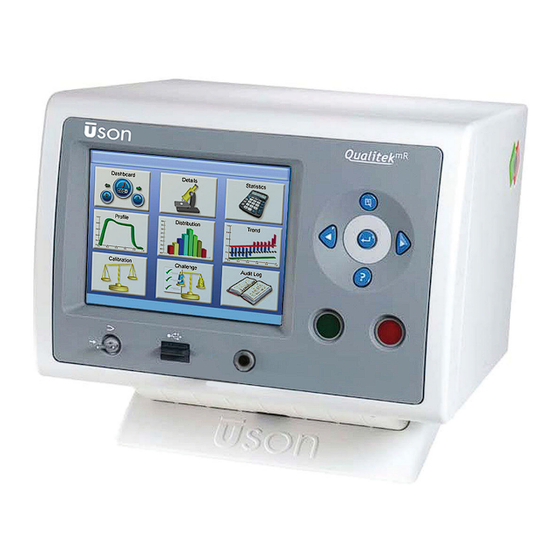
Page 28: Front Panel
4.2 Front Panel The front panel of the Qualitek mR is shown below. The panel has a navigation pad, stop and start buttons, a security lock switch, and a USB port. Touch Panel Screen Navigation Pad Start and Abort Buttons... -
Page 29: Navigation Pad
4.2.2 Navigation Pad The Navigation Pad has 5 buttons and a touch-sensitive ring (called the scroll pad) around the central button. Graphics on each button show what function it performs. Menu Button Scroll Pad Enter Button The center button is Enter. It can be used with the scroll pad to accept a selection that has been highlighted. -
Page 30: Security Key
4.2.3 Security Key Qualitek mR is in Run mode when the key is horizontal. Turn the key to the vertical position for Program mode. Changes made in Program mode are saved only when the key is used to return to Run mode. -
Page 31: Back Panel
4.2.5 Back Panel The back panel below is from a Qualitek mR outfitted as a Differential Pressure Decay tester. The appearance will vary depending on the options and tester type chosen. 1. Power Switch 8. Serial Port 2. Power Receptacle 9. -
Page 32: Differential Tester Module
The port is also known as a s Sealed Component Reference Port. METERED VOLUME This port is provided to connect reference volumes in sealed component and blockage testing applications. Qualitek mR Owner’s Guide... -
Page 33: Test Parameters
When Test Parameters are Available If existing test values are at hand, begin by simply entering those values into the Qualitek mR. Once all values are set correctly, the Qualitek mR is ready for fine tuning. When Test Parameters are not Available If there are no established test values, some experimenting is needed to arrive at values for pressures, flow rates, and times best suited to the product. -
Page 34: Fast-Track Setup
Set communication values for the connected peripherals, if used. Turn the security lock switch to Run position. Qualitek mR is now ready to use. 4.3.1 Put Qualitek mR to Work When everything is programmed and checked out, you’re ready to put Qualitek mR to work and start testing products. -
Page 35: In Case Of Difficulty
• Is the power supply connected to the back panel and is it receiving power (the power supply’s green light is lit)? • Is supply air connected to Qualitek mR? • Is the supply air clean and dry? Air that contains moisture, oil, or hard particulate will damage Qualitek mR. -
Page 36: Chapter 5: Run Mode
Run Mode Chapter 5 5.1 Home Screen Features Tapping the program name at the right side of the Title Bar from any screen where it is visible will call up the Program Selection screen. Select a program by entering it’s number in the Program data box. The program number can be selected in two ways. - Page 37 Move the data entry cursor back by one space each time it is pressed to allow correction of a mis-typed entry. Cancel Quits the process and returns to the previous screen. Any change in the entry will be discarded. Accepts the entry and returns to the previous screen. Qualitek mR Owner’s Guide...
-
Page 38: Usb Keyboard
Selecting a Program: Method 2 Tap the Program data bar to use the Run Mode Dashboard (Current Program) numeric keypad. Run Mode Dashboard (Current Program) Program Program Name Descriptive Program Name #1 Keypads appear when it is necessary to enter characters or numbers in a data bar. -
Page 39: Run Mode Home Screen
The USB Ready indicator shows if an inserted memory stick is ready for use. The USB memory stick is ready to use when the figure is unbroken according to the example below. USB memory not ready USB ready Qualitek mR Owner’s Guide... - Page 40 That Status Bar has a “ready-to-test” indicator. When the indicator is green the tester is ready to begin testing. If the indictor is red, a prerequisite is not being met. Ready to Test Not Ready Touching the indictor will display a list showing which prerequisites are being met and which are deficient.
-
Page 41: Quick Printing
5.2.1 Quick Printing The Qualitek mR tester provides a convenient method to print the configuration settings. This feature is available from almost every screen in the tester in both Run mode and Program mode. Use this feature to aid in such tasks as maintaining a record of the tester’s configuration, and also to confirm that the desired... - Page 42 The illustration below shows the first page of a Program Test Setup report. The report can be scrolled to view it completely. If desired, use the PDF export button to save the report as a PDF file to a USB memory stick.
- Page 43 Make the desired entries and press OK to print to the printer. Press Cancel to close all dialog boxes and return to the Home screen when finished using the Print feature. Qualitek mR Owner’s Guide...
-
Page 44: Double Diamond And Header Display
5.2.2 Double Diamond and Header Display A prominent feature on many Run mode screens is the double diamond indicator that shows the status of the tester or the result of the last test. Colors and highlighting emphasize the status so that the display can be interpreted at a glance. Descriptive text, e.g. -
Page 45: Run Mode Icons
• Challenge: See "Challenge" on page 5-34. • Audit Log: See "Audit Log" on page 5-36. Note that the Calibrate button is “grayed out” (dimmed) if a Leak Rate test is not selected. (See page 5-11.) 5-10 Qualitek mR Owner’s Guide... -
Page 46: Calibrate Button Availability
5.2.3.1 Calibrate Button Availability The Calibrate button is available only when the Measure Type of the current program is set to Leak Rate and Pressure Decay as shown. (The test type is set in Program Mode. See "Specifications" on page 6-4.) Otherwise, the button is dimmed and not available for use. -
Page 47: Symbols
The red x shows that the step failed or that the step result is failed. Basically, it indicates NOT OK. The symbols listed above have the same meaning on every screen where they may appear. 5-12 Qualitek mR Owner’s Guide... -
Page 48: Dashboard
5.2.5 Dashboard The Dashboard display is useful for monitoring tests in progress on a step-by-step basis. In many cases this will be the primary display preferred for watching tests as they proceed. Tapping the area to the right of the “double diamonds” will show the Statistics screen (See "Statistics"... -
Page 49: Dashboard Screen Elements
A condensed version of the Details display is shown in the middle of the screen. Active Program Progress Indicator The test progress is graphically shown as the rectangular bar at the bottom of the dashboard screen expands from left to right. 5-14 Qualitek mR Owner’s Guide... -
Page 50: Dashboard Options
5.2.5.2 Dashboard Options The dashboard gauges simplify the analysis of how the product and tester are performing during a test. The Dashboard gauges can be customized to further enhance the ease of monitoring the operation of the tester. Tapping any of the gauges will open the Dashboard Options screen shown below. -
Page 51: Details
Symbols (far right column): Graphical indicators appear in the right column to show if the step completed successfully or if there was a problem. For definitions of the symbols used: See "Symbols" on page 5-12. 5-16 Qualitek mR Owner’s Guide... -
Page 52: Input - Output Status Bar
5.2.6.1 Input - Output Status Bar The informative bar at the bottom of the Details screen shows the status of Inputs and Outputs. Outputs When Illuminated Ready Ready to test Busy Tester is busy Pass Test has Pass result Salvage Test has Salvage result Fail Test has Fail result... -
Page 53: Digital I/O Status
This display has the most complete information if the expanded I/O option is installed. The status of the inputs and outputs is shown according to this code: • * (asterisk) Disabled • ON • OFF 0 (zero) • X Don’t care 5-18 Qualitek mR Owner’s Guide... -
Page 54: Statistics
5.2.7 Statistics Constantly-updated accumulated statistics are shown on this screen. The displayed statistics are for the current program only. The Statistics option provides: • Minimum, Maximum results • Average results • Standard Deviation results • CPK results Statistics Counts are shown for: passed tests, salvaged tests, failed tests, total tests, and aborted tests. - Page 55 If any test is aborted, a row is added to the chart to show the aborted test information. The following illustration shows how this appears in action. “Aborted Tests” is shown only if at least one test has aborted 5-20 Qualitek mR Owner’s Guide...
-
Page 56: Profile
5.2.8 Profile The Profile screen shows a plot of the current test referenced either to Gauge or Differential pressure. Profile The Profile graph shown above and in the following illustration typical for Gauge Pressure. Selecting the Differential Pressure button will make the y-axis move up to the middle of the graph so that plus- and minus deviations from zero can be graphed. -
Page 57: Using The Scroll Pad
The scroll pad can be used to move the graphic plot as shown in the illustration below. The reset button is used to return the scale to default values whenever desired. Reset button The scroll pad can be used to move the plot along the axes. 5-22 Qualitek mR Owner’s Guide... -
Page 58: Profile Options Screen
5.2.8.2 Profile Options Screen Tapping the graph along an axis opens the Profile Options screen which allows changing the axis values. A smaller version of the graph is shown along with controls that can change the axis values. When the axis values are changed, the graph scaling is changed to alter the plot size or offset it from the original position. -
Page 59: Distribution
A running total of counts may be viewed in the area below the graph. The following counts are displayed: • Test Cycles • Passed • Salvaged • Failed Distribution 5-24 Qualitek mR Owner’s Guide... -
Page 60: Distribution Options Screen
5.2.9.1 Distribution Options Screen Tapping the plot area along either axis opens the Distribution Options screen shown in the following illustration. Use the Distribution Options screen to set the following parameters: • Minimum Result • Number of Bins • Maximum Result The Options can be saved and transferred to the main Distribution screen by selecting Done or discarded by pressing Cancel. -
Page 61: Trend
There is one plot point for every test that has been run. The plot can be easily repositioned in the display area by touching the plot and dragging it to a new position. 5-26 Qualitek mR Owner’s Guide... - Page 62 The trend plot can be filtered with the Passed, Salvaged, and Failed buttons to include any or all of those test results on the plot. The trend results of all test outcomes are displayed because all filter buttons are pressed as shown. Shown are the results of 19 passed tests.
-
Page 63: Using The Scroll Pad
The effect of this is shown in the illustrations to the right. Touch the plot and drag it to further adjustment its position, if desired. The scroll pad was turned clockwise. 5-28 Qualitek mR Owner’s Guide... - Page 64 Accompanying the ability reposition the plot by touching and dragging it, the Arrow Keys are also useful for adjusting the plot position as shown in the following illustration. The original trend plot is shown above. The Left/Right arrow keys are used to move the x-axis to the left or right which shifts the plot accordingly.
-
Page 65: Reset Button
The reset button is available for use to return the scale to the original values whenever desired. Reset button These 3 buttons are used to select the results to be included. In this illustration, all of the buttons are pressed. 5-30 Qualitek mR Owner’s Guide... -
Page 66: Trend Options Screen
5.2.10.3 Trend Options Screen Tapping the axes of plot area on either of the graph axes will open the Trend Options screen. This screen allows fine tuning the range of the axes so that the desired areas can be seen in detail. Changes made here will carry over to the main (previous) screen when Done is selected. -
Page 67: Calibrate
Calibration screen. Note: the SNR number of 0.2 displayed in these figures is for a differential tester. For a gauge tester, the SNR number will be 0.5. Step-by-step Instructions are given on the status bar. 5-32 Qualitek mR Owner’s Guide... -
Page 68: Calibrate Button Availability
Leak calibration is a two-step process. First, the test is run with a non-leaking master part to establish the characteristic pressure change of the part and the pneumatic system. This result is referred to as the Comp value. The second test is run with a traceable Leak Master (e.g., traceable to the NIST in the USA) to introduce a known leak to the master part. -
Page 69: Challenge
• Details • Profile Tapping within the area of a column will make that column active. In the screen shown below, the No Leak Challenge column has been made active (is shown in yellow color.) 5-34 Qualitek mR Owner’s Guide... - Page 70 As previously mentioned, it is possible to switch back and forth between the No Leak Challenge and Known Leak Challenge columns my tapping within the column. This concept is shown in the following illustrations. Below, the No Leak Challenge column is highlighted, so the operator is prompted to attach a non- leaking part for the test.
-
Page 71: Audit Log
Hardware Setup tab in Program Mode. Audit Log Touch and drag the Scroll Bar at the right side of the log to move up or down in the list. The scroll pad can also be used to the same effect. 5-36 Qualitek mR Owner’s Guide... - Page 72 All results are shown in the log because all filter buttons are pressed. Only “Fail” results are shown. For an explanation of the symbols used in the P/F column, See "Symbols" on page 5-12. Run Mode 5-37...
-
Page 73: Chapter 6: Program Mode
6.1 Program Mode Program Mode is where all the operating options and parameters of the Qualitek mR are established. Unlike Run Mode, settings can be made in Program Mode that greatly affect the operation of the tester, so only authorized persons should use this mode. -
Page 74: Screens In Program Mode
Enter Button can be used to Digital I/O Port make the selection. Data Box with Check Box Backlight Timeout Tap the central box to toggle the checkmark. The checkmark shows the function is enabled, in this case, the Backlight. Qualitek mR Owner’s Guide... -
Page 75: Test Setup
6.2.2 Test Setup This screen gives an overview of the main settings for the selected program. The tabs, in this case 6 of them, are used to move to different screens in Test Setup. The screens are: • Specifications. See "Specifications"... -
Page 76: Specifications
• Differential Mass Flow test • Force Mode Test • Vacuum Mode Test Measure Type Measure type selections are dependent on test type selections. Select either: • Leak Rate: Measures the rate of change of pressure or flow Qualitek mR Owner’s Guide... - Page 77 • Pressure Change: Measures the cumulative loss of pressure. • Flow: Measures flow. • Pressure Measure: Measurement of pressure. • Force Change: Movement from a state of rest. The force sensor detects the change from the first measurement to the last measurement made during the test phase (delta force).
- Page 78 Using the Salvage feature can be very useful in casting applications or where the Qualitek mR is being used in an automatic production line where the component can be automatically directed to a rework station for repair.
-
Page 79: Coupling
6.2.2.2 Coupling This screen is used to set the coupling parameters for coupling fixtures. Coupling may be turned off, if it is not required, by setting the couple duration to zero. When coupling times are set, the coupling steps are automatically included as implied steps in the current program. - Page 80 The illustration above shows that 4 coupling times are set which will add 1 second of coupling time to current program. Use the buttons in the Couple 1 and Couple 2 Output columns as needed to use the desired couple for the step. If Off, the couple will not activate. Qualitek mR Owner’s Guide...
- Page 81 The Coupling 1 and Coupling 2 always occur in order at the start of the test and Uncoupling 2 and Uncoupling 1 will occur at the end of the test. If text is entered in Description, then that descriptive name will be used whenever appropriate.
-
Page 82: Steps
Auto Zero The Qualitek mR’s Auto Zero feature helps to maintain accuracy by eliminating any long-term zero drift (caused by environmental changes) by venting the sensors to atmosphere during the Auto Zero step. The subsequent reading is then used as the new zero value (reference point) for the current test. - Page 83 Connect The DMF (Differential Mass Flow) test type includes a Connect step used to pressurize the test port. Once the pressure is within the preset limits (indicating a component has been connected), pressurizing stops before proceeding with the test cycle. The default regulator for the connect step is Regulator 1.
- Page 84 To assign the regulator(s) to use in each fill/evac step, tap the label for Fill/Evac 1 or Fill/Evac 2 to view the Fill/Evac Step Options screen. The selections available are limited by the installed regulators, of course. An example of this screen is shown below: 6-12 Qualitek mR Owner’s Guide...
- Page 85 Stabilize This option sets the time period during which the pressure and temperature is allowed to stabilize before a leak rate measurement is performed. Equalize This parameter allots a duration allowing the differential test chambers to adjust to tare and become ready before starting the measurement step. The tester will automatically pick the best default time for this step but it may be changed manually, if so desired.
- Page 86 Uncheck exhaust test part box and select Done. Next, set Vent Time to zero. If the vent output is disabled, the test part may remain pressurized; use care when disconnecting the test part. Set the Vent time: Used to open the part under test to atmospheric pressure. 6-14 Qualitek mR Owner’s Guide...
-
Page 87: Regulators
6.2.2.4 Regulators This screen shows the regulator(s) configured for the tester. Regulators can be either manual or electronic. If the tester is equipped with the electronic regulator option, the control method will be enabled. The control method has three controls: •... -
Page 88: Linking
This allows confirmation of the progress of linked programs. It is possible to choose a specific venting behavior for each result by using the Vent Enabled box in the Linking Setup. Choose to enable or disable the vent with the checkbox. 6-16 Qualitek mR Owner’s Guide... -
Page 89: Calibration
6.2.2.6 Calibration Calibration values for the currently selected test can be set by navigating to the Program Mode, Test Setup, Calibration tab. Each program needs to be calibrated individually and if any of the test parameters are changed, including the volume of the test component, a re-calibration should be performed. - Page 90 • Pressure Correction: The pressure correction feature is used to correct flow reading due to pressure variations. Select the desired pressure correction method: Disabled, Factor, Absolute, or Gauge. (See “Pressure Correction Setup” later in this document.) 6-18 Qualitek mR Owner’s Guide...
- Page 91 Disabled: No correction pressure applied. Factor: The correction method applied is: Corrected flow = measured flow + ((test pressure - measured pressure) * factor). Absolute: The correction method is based on ratio of absolute pressures: Corrected flow = measured flow * (test pressure + atmosphere) / (measured pressure + atmosphere) Gauge: The correction method is based on the ratio gauge pressures:...
- Page 92 Pressure Correction Setup The Qualitek mR’s Mass Flow and Differential Mass Flow models include a pressure correction option. In some applications, when you apply pressure to a part, flow variations may occur that affect the accuracy of the test reading. The pressure correction option is used to minimize this affect by adjusting the reading for flow variations caused from the applied pressure while under test.
- Page 93 The TC Method selections are: Disabled: Temperature compensation is disabled for the selected program and associated parameters are hidden. Enabled: The temperature compensation test steps are performed and the compensation is applied. Apply Only: The temperature compensation information from a previous test is applied.
-
Page 94: Digital I/O
(See "Digital I/O" on page 6-67.) Note that if a step has a zero time duration or is otherwise not being used in a test, it is not available on this screen for customization. 6-22 Qualitek mR Owner’s Guide... - Page 95 The output states for a step may be set to: Pulse at Step Start Pulse at Step End The Digital Inputs tabs works is similar manner to Digital Outputs, however the selections for Input State are not the same choices that were available for Digital Outputs: For Inputs that may be configured, the settings...
-
Page 96: Service
• Export. See "Export" on page 6-27 • Import. See "Import" on page 6-28 • Maintenance. See "Maintenance" on page 6-29 • License. See "License" on page 6-31 • Diagnostics. See "Diagnostics" on page 6-32 Service 6-24 Qualitek mR Owner’s Guide... -
Page 97: Data Management
6.2.3.1 Data Management The Data Management screen has four buttons which are used to clear the following logs and counters: • Clear Audit Log • Clear All Counters • Clear Log and Counters • Clear Alert Counters Pressing the button performs the action immediately. Be sure to have printed or otherwise saved any data that may be needed for future use. -
Page 98: Login Test
Under the login test tab, you can test passwords for: • Operator • Supervisor • Administrators To test a password, enter the password you want to check into the appropriate field, then click the corresponding button. 6-26 Qualitek mR Owner’s Guide... -
Page 99: Export
6.2.3.3 Export Data that can be exported from the tester: • Complete Backup (All of the above) • All Programs • Single Programs • User Options and Settings • Hardware Calibration • Audit Log and Statistics • Factory Configuration • XML: Audit Log and Statistics •... -
Page 100: Import
The USB ready indicator on the status bar will show when the USB device is ready. Press the import button. Once the data transfer is complete, restart the tester. 6-28 Qualitek mR Owner’s Guide... -
Page 101: Maintenance
6.2.3.5 Maintenance This screen allows updating the tester software by using the Update Software button. The update file must be on a USB memory stick inserted in the front panel USB slot. Set Factory Defaults The Set Factory Defaults button is pressed to reset all tester settings to factory default values. - Page 102 Follow any on-screen prompts that may appear and follow the instructions they give. When the update process is complete, restart the tester. Install Patch This button will be used should Uson issue a patch to the software. Instructions for installing the patch will be provided at that time. 6-30...
-
Page 103: License
6.2.3.6 License The License tab shows important information about the terms and features of the installed license. "License Updates" on page 10-1 for detailed information about installing or updating a license. Program Mode 6-31... -
Page 104: Diagnostics
• Bar Code Scanner Diagnostic • PWM Output • Scrollpad Diagnostic To Exit any diagnostic menu, select the Diagnostic Tab, then select the Reset Tests button. Tester diagnostic selections may vary depending on tester specifications. 6-32 Qualitek mR Owner’s Guide... - Page 105 Analog-to-Digital Subsystem Test The Analog to Digital subsystem screen allow viewing the sensor(s) raw data. Valve Outputs Diagnostic The Valve Outputs screen is used for testing internal valve(s) 1 to 16. Program Mode 6-33...
- Page 106 The Standard Digital Inputs screen is used to test standard digital inputs 1 to 16. Standard Digital Outputs The Standard Digital Outputs screen is used to test these digital outputs: pass, fail, ready, EOC, alarm, and audio. 6-34 Qualitek mR Owner’s Guide...
- Page 107 Expanded Digital Inputs The Expanded Digital Inputs screen is used to test the expanded digital inputs 1 to 8. Expanded Digital Outputs The Expanded Digital Outputs screen is used to test expanded digital outputs 1 to 16. Program Mode 6-35...
- Page 108 If the bar code scanner is connected but does not scan, recycle tester power while it is connected so that the tester can recognize the scanner. PWM Output The PWM Output menu allows checking the voltage to the electronic regulator. 6-36 Qualitek mR Owner’s Guide...
- Page 109 Scrollpad Diagnostic This screen allows testing the scroll pad board. To perform the Scroll Pad Diagnostics (Key/Wheel): 1. Press the ‘Top key’ of the overlay keypad; you should see the value in the ‘Key’box change to 0x01. Release the Top key; the value should return to 0x00.
-
Page 110: Options
"Tester Control" on page 6-45 • E-mail Setup. See "E-mail Setup" on page 6-48 • Passwords. See "Passwords" on page 6-50 • General. See "General" on page 6-54 • Bar Code. See "Bar Code Option" on page 6-54 Options 6-38 Qualitek mR Owner’s Guide... -
Page 111: Results Logging
6.2.4.1 Results Logging Results logging is customized from the screen. Audit Logging Enable Status • This box is automatically checked when the settings on this screen have been set to allow an audit log to be created. Audit Log Format •... - Page 112 Pressing Customize will open the Log Custom Format display as shown below. If no custom log has ever been created, or if the entire previous log setup has been deleted, then the window will have no entries as shown 6-40 Qualitek mR Owner’s Guide...
- Page 113 An easy way to populate the screen with the default custom settings is to press the Apply Defaults button. The screen will now appear as shown below. Tapping an item in any of the columns will begin the process of customizing that item, if available.
- Page 114 This is helpful for formatting the output so that it is more easily readable or for preparing it for importing into an application as a tab- delimited file for a spreadsheet, for example. 6-42 Qualitek mR Owner’s Guide...
- Page 115 A new line (Id#) may be inserted by pressing the Insert button as shown below. A maximum of 30 Id#s may be used. To delete a line, highlight it and press the Delete button. After the desired changes are made, press the Done key to accept them. Data Logging to USB Memory Stick Before inserting a USB memory stick it is important to use the key to switch to Program Mode.
-
Page 116: Alerts
2. Switch the Program/Run key to Program Mode, and then remove the USB memory stick. Removing the stick before switching to the program mode leaves the file open and unreadable. 6.2.4.2 Alerts Alerts will be issued when tests meet the conditions established on the Alerts tab. 6-44 Qualitek mR Owner’s Guide... -
Page 117: Tester Control
6.2.4.3 Tester Control Use the Tester Control screen to set how the tester is to be controlled. Program Selection Source May be set to: • Program Mode: allows program selection only from within Program Mode. Program selection will be locked in Run Mode. This will prevent changing program selections by an operator without the Security Key. - Page 118 Choose from: • Normal • Auto Repeat • Continuous Fill The Continuous Fill option found in the end-of-cycle actions is used to maintain air pressure at the part as an aid in locating a leak. 6-46 Qualitek mR Owner’s Guide...
- Page 119 Fail End-of-Cycle Action Choose from: • Normal • Auto Repeat • Continuous Fill • Continuous Fill Including Gross The Continuous Fill Including Gross option found in the fail end-of-cycle actions is only active after any step fails its limits, and used to continuously maintain air pressure at the part as an aid in locating a leak.
-
Page 120: E-Mail Setup
Use the E-mail Setup tab to select e-mail alerts and account settings. Alerts established on the Alerts tab (See "Alerts" on page 6-44) can be selectively sent via e-mail. Check the box for each alert type to use. 6-48 Qualitek mR Owner’s Guide... - Page 121 Use the E-mail Account tab to establish the parameters for your site’s setup. You may need the help of your site IT professional to assist with providing the correct values to enter. The email option is only available when the Ethernet option is purchased. Program Mode 6-49...
-
Page 122: Passwords
Has full control of the tester but is not able to change the network functions of the tester such as IP addresses. Administrator: Shares the functions of the Supervisor level and also has access to the IT functions of the tester so network settings may be made. 6-50 Qualitek mR Owner’s Guide... - Page 123 The Lock Symbol The lock appears in top right corner of the display when a password exists. If the symbol is shown as locked, a logon is required to access Program Mode features. The symbol displays unlocked status whenever a numeral (1, 2, or 3) is superimposed on it.
- Page 124 Touch the status bar and the pop-up menu will appear as shown below. Select Login/Logout. Forgotten Password Call Uson to obtain a reset code. Select Forgot Password from the pop-up menu and enter the code and select OK. This action clears all passwords. 6-52...
- Page 125 Select the appropriate user to login from the drop down menu in the User bar. Then touch the Password bar below it to open the keyboard and enter the password. Press OK to close the keyboard and return. Then, press the Login button to complete the login.
-
Page 126: General
Tester Control tab must be set to use one or both of the features. The sample display below shows that both features have been selected. When either or both of these features are selected, further settings are made available on the Bar Code tab. 6-54 Qualitek mR Owner’s Guide... - Page 127 The scanner may be connected to either the front or rear USB port. The tester should be off while the scanner is connected. If the scanner is connected while the tester is powered on, the scanner will not work until the tester power is recycled. Be sure to configure the scanner to output CRLF at the end of the scan string.
- Page 128 • Add Scan: Press this button to activate the keyboard to enter the desired Scan Key. • Remove Scan: Tap the Id# of the Scan Key to highlight it and then press Remove Scan to delete that scan from the list. 6-56 Qualitek mR Owner’s Guide...
-
Page 129: Hardware Setup
6.2.5 Hardware Setup Hardware Setup has 7 tabs: • Sensors: See "Sensors" on page 6-58 • Serial Port: See "Serial Port" on page 6-58 • Printer: See "Printer" on page 6-60 • Network: See "Network" on page 6-61 • Digital I/O: See "Digital I/O"... -
Page 130: Sensors
6-10. Sensor Calibration Contact a qualified Uson representative for sensor calibration. 6.2.5.2 Serial Port The serial port settings are made at this screen. To learn the correct settings to use you must consult the documentation that was provided with your device. - Page 131 Baud Rate: 1200, 2400, 4800, 9600, 19200, 38400, 57600, or 115200 Data – Parity – Stop Bits: 8 – none – 1 8 – even – 1 8 – odd – 1 7 – none – 1 7 – even – 1 7 –...
-
Page 132: Printer
Examples of things that may be printed: • Program Test setup • Options • Hardware setup • Factory setup • Audit log • Details screen • Values for the following screens: Profile Trend Statistics 6-60 Qualitek mR Owner’s Guide... -
Page 133: Network
Qualitek mR has the capability to log to a file on the network. The Qualitek mR opens a log file when going from Program Mode to Run Mode. During this time, the file is actively used (open) by the tester. Attempts to delete, change, or move the file by other means are blocked by the network. - Page 134 Host & Domain Name The host name is a unique name for this Qualitek mR tester. An example of a typical host name might be: “qmr-001”. The domain name is relative to the network to which the tester is connected. The network administrator can provide the domain name.
- Page 135 Ethernet Port The physical Ethernet port on the Qualitek mR tester must have an IP address assigned to it relative to the network it is associated with. There are two ways to setup the IP address: • Automatically (via DHCP) •...
- Page 136 This parameter is defined by the network administrator. After the preceding parameters have been entered, save them to the database by turning the key to Run mode, power the tester off and on again, and proceed to Windows Server tab. 6-64 Qualitek mR Owner’s Guide...
- Page 137 Windows Server Qualitek mR audit logging can be set to the “Windows Network.” Before this can happen, the Windows Server parameters must be entered and a network connection made. Also, before we can connect to a Windows Network, all preceding steps...
- Page 138 The network pathname is the directory path under the Windows Server share name. The simple case is where there is only one Qualitek mR (QMR) tester. An example pathname is “/qmr”. However, this will not work when more than one QMR tester is logging.
-
Page 139: Digital I/O
6.2.5.5 Digital I/O (Available on testers equipped with expanded Digital I/O only.) The digital I/O can be customized to a high degree. Settings made here will apply to the tester in a global fashion. Changes can also be made locally to a test by further customizing the settings using the Digital I/O tab in the Test Setup screen. - Page 140 The step result output will be set at the end of the specified step based on the step result and will be held on for the duration of the test. The step result output is cleared under normal operation with the standard result outputs. 6-68 Qualitek mR Owner’s Guide...
- Page 141 Available assignments for the digital inputs are: • Disable • Program Specified (Allows setting the output in a program. See "Digital I/O" on page 6-22.) Program Mode 6-69...
-
Page 142: Audio
• High Use Generate Sample Tone to preview the tone at the selected volume and duration. The result audio duration maximum limit is 60 seconds. The beep audio duration maximum limit is 5000ms (5 seconds). 6-70 Qualitek mR Owner’s Guide... -
Page 143: Clock
6.2.5.7 Clock This screen is where the time, time format, and date are set. The correct time setting is important for accurate time stamps and logs. The large calendar displayed here shows the current date and time setting. If a discrepancy is noted in the date or time it can be set correctly at this screen by using the touch screen functions to change the values. -
Page 144: Display
You can prolong the backlight lifetime by setting the brightness level no brighter than necessary for adequate visibility and using the backlight timeout to turn off the display during periods of inactivity. 6-72 Qualitek mR Owner’s Guide... - Page 145 Calibrate Touch Screen If the touch screen fails to accurately respond to input, use the Calibrate Touch Screen button on the Display tab. When selected, the tester will display the calibration screen the next time it is powered up.. calibration utility Touch crosshair to calibrate While powering up, just before the Home screen would normally appear, the calibration screen will appear as shown above.
-
Page 146: Modbus
Programmer or System Integrator. Press the Set Default button to set the Modbus Editor to default settings. See "QmR Modbus" on page 9-1 for a detailed discussion of the nomenclature and registers used in the Mapping Tab. 6-74 Qualitek mR Owner’s Guide... -
Page 147: General
Modbus Registers Tab Settings This tab is where you configure your system’s Modbus registers. An example of this screen is shown below. Normally, these settings will be provided by, or are made by, your site Programmer or System Integrator. 6.2.5.10 General Spool Valve Check: The General tab includes a Spool Valve Check feature that monitors the status of the equalization valve during a differential pressure decay test, and aborts the test and reports an error if it detects the valve is in the wrong... -
Page 148: Factory Setup
6.2.6 Factory Setup The screens in Factory Setup are read-only, meaning the data cannot be changed except by authorized Uson personnel. The screens, however, contain useful information that can be readily viewed. Factory Setup Factory Setup has five tabs. They are: •... -
Page 149: Tester
6.2.6.1 Tester The Tester tab shows important information about the tester. This information may be requested by Uson support if help is necessary. At this screen, the following may be seen: • Tester Model Type • Configuration Code • Serial Number •... -
Page 150: Pneumatics
• Couple Outputs: The number of installed couple outputs, 4 Max. • Auxiliary Flow Function: Configuration or not installed. • Downstream Sensor: Configuration or not installed. • Venturi: Checked if installed. • Internal Leak Master: Checked if installed 6-78 Qualitek mR Owner’s Guide... -
Page 151: Sensors
6.2.6.3 Sensors This screen shows important information about the installed sensors. Sensor information which may be seen here includes: • Sensor Type • Sensor Range • Number of Positive Calibration Points • Number of Negative Calibration Points • Sensor Vacuum: Yes or No Program Mode 6-79... -
Page 152: Regulators
6.2.6.4 Regulators This screen is a convenient place to see they type and range of the installed regulator(s). 6-80 Qualitek mR Owner’s Guide... -
Page 153: Add-Ons
6.2.6.5 Add-Ons The status of various optional add-ons can be seen at this screen. The following items can be viewed: • Fieldbus Interface Option • Ethernet Package: Installed or Not Installed • Expanded Digital I/O Option: Installed or Not Installed •... -
Page 154: Chapter 7: Basic Testing
Basic Testing Chapter 7 7.1 Basic Testing 7.1.1 Test Cycle For normal operation, the component is connected to the test port of the unit and the Start button is pressed. In a differential tester, the tester pressurizes the test component and a reference volume. -
Page 155: Test Results: Pass, Fail, And Salvage
During the Vent Phase, the test component is vented to atmosphere. 7.1.3 Test Results: Pass, Fail, and Salvage The Qualitek mR makes it very easy to determine the test results. The display will clearly indicate Pass, Fail, or Salvage at the end of the test. Also, the simulated indicator lights of the Uson double-diamond logo will brighten in color to indicate the status. -
Page 156: Sealed Component Test Steps
too short, temperature effects or component expansion may cause erroneous results during the test phase. Limits In order to set a realistic test limits, the maximum admissible leak rate of the test component must be determined. This can be obtained from component specifications, trials, comparisons with previous test components or any other reliable source of information. -
Page 157: Chapter 8: Reference
Uson stands ready to meet all of your servicing and calibration requirements. Your Uson Representative is the best source of information about these services and will help you make arrangements to send your tester to Uson for service. Please contact the Uson Customer Support Hotline at (+1) 281-671-2000 or your Uson Representative for further information on calibration and maintenance services from Uson. -
Page 158: Connection
DTE device (the QmR). As always with serial communication, both devices must be set to identical baud rates or the data will be scrambled or lost. Qualitek mR Owner’s Guide... -
Page 159: Standard Output Timing
8.4 Standard Output Timing Reference... -
Page 160: Valve States
8.5 Valve States Following are charts detailing the valve implementation for the different models of Qualitek mR. Qualitek mR Owner’s Guide... -
Page 161: Diff. Pressure Decay Valve Sequence
8.5.1 Diff. Pressure Decay Valve Sequence 2/4/0 Uson Qmr Differential Pressure Decay Leak Test Valve Sequence X = Output On X/R = Output Latched on Reject Test Sequence - Normal Production Test Cycle Test Sequence - Normal Production Test Cycle... - Page 162 Pressurize using Reg 1 or 2 (Check Gauge Pressure) i l i Stabilize (Gross Leak Gauge) i l a Equalize (Gross Leak Differential) Fine Leak Test (pressure change/ tared value only) Exhaust Disengage Coupling Port 2 Disengage Coupling Port 1 EOC Return to Ready. Qualitek mR Owner’s Guide...
-
Page 163: Diff. Pressure Rise Leak Test Valve Sequence
8.5.2 Diff. Pressure Rise Leak Test Valve Sequence 2/4/09 Uson Qmr Differential Pressure Rise Leak Test Valve Sequence X = Output On X/R = Output Latched on Reject Test Sequence - Normal Production Test Cycle Test Sequence - Normal Production Test Cycle... -
Page 164: Gauge Press. Decay Leak Test Valve Sequence
Pressurize using Reg 1 or 2 (Check Gauge Pressure) Isolate regulator supply. Stabilize (Gross Leak Gauge) Fine Leak Test (pressure change/ tared value only) Exhaust Disengage Coupling Port 2 Disengage Coupling Port 1 EOC Return to Ready. Qualitek mR Owner’s Guide... -
Page 165: Mass Flow Test Valve Sequence
8.5.4 Mass Flow Test Valve Sequence Reference... -
Page 166: Diff Mass Flow Leak Test Valve Sequence
8.5.5 Diff Mass Flow Leak Test Valve Sequence 8-10 Qualitek mR Owner’s Guide... -
Page 167: Back Pressure Flow Test Valve Sequence
8.5.6 Back Pressure Flow Test Valve Sequence Reference 8-11... -
Page 168: Standard I/O Operation
(INRTN). The outputs are dry contact relays. If desired, it is possible to supply 24VDC to the (-) side of each of the outputs, and then when the output is asserted, there would be a 24VDC signal present on the (+) side. "I/O Port Pinout" on page 8-13. 8-12 Qualitek mR Owner’s Guide... -
Page 169: I/O Port Pinout
8.7 I/O Port Pinout Digital I/O 1 DB-25 connector on the rear panel: Function STARTIN Operation of the standard I/O is as ABORTIN follows: The inputs are opto-isolators requiring BCD1IN 24VDC power with respect to pin 19 BCD3IN (INRTN). The outputs are dry contact relays. -
Page 170: Expanded I/O Port Pinout
8.8 Expanded I/O Port Pinout The expanded I/O assignments are configured by the user. The following illustrations below and on the next page show the hardwiring. 8-14 Qualitek mR Owner’s Guide... -
Page 171: Digital I/O Power Rating
8.9 Digital I/O Power Rating The I/O connector is used to connect the Qualitek mR to a Programmable Logic Controller (PLC) or other automation equipment. Be aware that it is possible to damage the interface when connecting to non-PLC loads such as incandescent lamps, valves, or other high-inrush devices. -
Page 172: Temperature Compensation (Temp Comp)
This document describes the setup and operation of the QMR Temperature Compensation option to minimize the effects of temperature changes on the pressure decay measurement. 8-16 Qualitek mR Owner’s Guide... -
Page 173: Equipment
• QMR Tester with software version 1.16.0 or later installed. • PC with Microsoft Excel application. • The Uson Temperature Compensation Excel spreadsheet Template. The following items may be required to transfer QMR results to the PC: • RS-232 9-way D-type Cable. -
Page 174: Test Setup
Program Mode Test Setup tabs. 8.10.3.3 Temperature Compensation Initial Setup. The Temperature compensation option is enabled by selecting the Program Mode Test Setup Calibration Temp Comp tab shown below and setting the required TC Method. 8-18 Qualitek mR Owner’s Guide... -
Page 175: Temperature Compensation Test Steps
The TC Method selections are: Disabled, temperature compensation is disabled for the selected program and associated parameters are hidden. Enabled, the temperature compensation test steps are performed and the compensation is applied. Apply Only, the temperature compensation information from a previous test is applied. -
Page 176: Results Logging
(CSV) format to simply the transferring of data to an Excel spreadsheet. Select the Program Mode System Options Result Logging tab below and set the Audit Log Format parameter to Custom. 8-20 Qualitek mR Owner’s Guide... - Page 177 Custom Log Format Select the Customize option and set the log format to produce a Comma Separated Value (CSV) output as shown below. This will allow files created by the logging process to be imported into Microsoft Excel and allow data to be easily transferred between spreadsheets. Reference 8-21...
- Page 178 Result Logging Network Pathname parameter. The USB Memory Device will log the result information at the end of each test to a folder on the USB memory device specified by the Result Logging USB pathname parameter. 8-22 Qualitek mR Owner’s Guide...
-
Page 179: Data Analysis
8.10.4.1 Uson Temp Comp Excel Template. Uson provides a Temp Comp spreadsheet on the CD shipped with the tester; or you may request one from your Uson representative. Copy the Uson Temp Excel spreadsheet to a suitable working folder on the PC and open the spreadsheet as shown below. -
Page 180: Establishing Calibration Compensation
10 rows when transferred to the Excel spreadsheet. Record the results for ambient parts and transfer the atmospheric and pressure measure step readings to the AT measure and Measure cells in the top 10 rows 8-24 Qualitek mR Owner’s Guide... -
Page 181: Establishing Temperature Factor
labelled Ambient products on the Excel Temp Comp spreadsheet's Compensation Template page shown below. Temperature Compensation Template Test No. TC Measure step Measure step result Modified TC Modified Measure Predicted Factor Compensated result Measure. Measure 0.02000 -0.01000 -0.01100 -0.01100 0.742 0.00234 0.03000 0.00000... - Page 182 The Temperature factor is automatically calculated based on the average of the predicted ratios in the lines between rows 13 and 20 of the Compensation Template tab. The QMR parameter page will now show the calculated Offsets and Temp Factor values in the respective windows. 8-26 Qualitek mR Owner’s Guide...
-
Page 183: Qmr Setup
8.10.5 QmR Setup The calculated offset and factors are now transferred to the QMR Calibration and Temp Comp menus. 8.10.5.1 Comp Offset If a calibration offset is required, select the Program Mode Test Setup Calibration shown below. Set the Measure Setup sub tab Comp Method to Normal and enter the Calibration Offset value into the Measure Setup sub tab Comp value parameter. -
Page 184: Verification
The QMR will now correct the test results according to the values entered and can now be verified by performing tests on known leak tight parts under normal operating temperature conditions with and without leak master. 8-28 Qualitek mR Owner’s Guide... -
Page 185: Stallion Force Decay Tester Model
8.11 Stallion Force Decay Tester Model The Stallion Force Decay Sensor screen shows important information about the installed sensors for the Stallion Force Decay. The sensor information includes the following options: • Sensor Type • Sensor Range • Number of Positive Calibration Points •... -
Page 186: Specifications
• Set up a force decay test • View and change important parameters of the selected program • Set up the additional testing parameters The Force Decay model uses three test types: • Force mode • Vacuum mode • Pressure Decay 8-30 Qualitek mR Owner’s Guide... -
Page 187: Force Mode Steps
8.11.2 Force Mode Steps The Steps screen shows all of the steps for a force test type. Unnecessary steps can be set to zero. Force mode uses the force sensor for all steps, except the Vent Step. The Fill step advances the program to the next step when the target pressure is achieved. -
Page 188: Force Mode Details (Run Mode)
Each row is a step in a program that was set up in the Program Mode. The Fill step advances the program to the next step when target force is achieved. 8-32 Qualitek mR Owner’s Guide... -
Page 189: Vacuum Mode Steps
8.11.4 Vacuum Mode Steps The Steps screen shows all of the steps for a Vacuum Test type. Unnecessary steps can be set to zero. Vacuum Mode uses the vacuum sensor for the Fill, Isolate, and Vent steps and the force sensor for the Stabilize and Measure steps. The Fill step advances the program to the next step when the target pressure is achieved. -
Page 190: Vacuum Mode Details (Run Mode)
The Vacuum Mode Details screen (Run Mode) shows the progress of the steps in the current program and any programs to which it is linked. The bottom of the display shows the status of relevant digital input and output. 8-34 Qualitek mR Owner’s Guide... -
Page 191: Bar Code Scanner Initial Setup
8.12 Bar Code Scanner Initial Setup If you have purchased the optional bar code scanner, assemble it according to the instructions below. CONNECTING THE CABLE Rubber gasket Plastic boot Cable spacer Cover Strain relief Align Slip the cover over the cable. - Page 192 Mode > System Options > General Tab > Language.) Please refer to the Quick Reference Guide that is packed with the scanner for additional information about operating the scanner. RESTORE DEFAULT RESTORE DEFAULT Ì$+$*oÎ INTERFACE SELECTION USB-COM Ì$+UA02$-4Î DATA FORMAT TERMINATOR CR-LF Ì$+EA120D0A$-ÃÎ 8-36 Qualitek mR Owner’s Guide...
- Page 193 LANGUAGE Select the language that is set in the QmR's Program Mode > System Options > General > Language screen Deutsch Ì$+FJ3$-$Î USA (Default) Ì$+FJ0$-|Î English Ì$+FJ4$-)Î Español Ì$+FJ6$-3Î Czech Republic Ì$+FJE$-~Î Svenskt Ì$+FJ5$-.Î Français Ì$+FJ2$-ÊÎ Japanese Ì$+FJ8$-=Î Russian (Latin) Ì$+FJ9$-BÎ...
-
Page 194: Internal Clock Battery Replacement
The earliest versions of Qualitek mR have a soldered-in battery. The tester can be returned to Uson for battery replacement or, if requested, Uson will ship a new battery and battery holder to the user for installation on-site. -
Page 195: Replacing Soldered-In Batteries
8.13.2 Replacing Soldered-In Batteries The following instructions are for those who wish to install a battery holder themselves and replace the battery. 1. Ensure the tester is powered off. 2. Remove the outer cover from the QMR tester and locate the battery on the printed circuit board (PCB). - Page 196 6. Replace the outer cover on the tester and power on the unit. When the unit has completed its boot-up, go to the Hardware Setup > Clock screen and reset the time. 8-40 Qualitek mR Owner’s Guide...
-
Page 197: Pneumatics Operation
8.14 Pneumatics Operation The tester employs electrically controlled pneumatic valves to supply compressed air (or other gas) for leak testing a component. The valves operate in a programmed sequence to pressurize a test component and a reference component or chamber. The test and reference components are then isolated from each other and a differential transducer is used to monitor the pressure difference between the two ports. - Page 198 8-42 Qualitek mR Owner’s Guide...
- Page 199 Reference 8-43...
- Page 200 8-44 Qualitek mR Owner’s Guide...
-
Page 201: Pressure Change Calc. (Leak Rate)
8.14.2 Pressure Change Calc. (Leak Rate) For test types such as Leak Rate, Qualitek mR calculates the leak rate from the pressure change over time using values derived from the following formulae. Variable Definitions for the Calculations: CalRate = Leak Master Leak Value (user-entered value) -
Page 202: Pneumatic Signal/Noise Ratio
Menu. The concept previously known to many as the “comp/cal ratio” is employed in the Qualitek mR as the Pneumatic Signal/Noise Ratio (PSN ratio). Like the Comp Value and Cal Value, the PSN ratio appears on the Calibration screen. 8.14.2.1 Pneumatic Signal/Noise Ratio The larger the PSN Ratio, which is the calibration value divided by the compensation value, the more repeatable the test will be. -
Page 203: Concepts Applicable To Testing
8.15 Concepts Applicable to Testing Pressure In physics, pressure is a force measured in terms of its distribution over an area of an opposing force. This is expressed as force (F) divided by unit area (A) of the surface area to which the force is applied. Air pressure most commonly refers to a force exerted uniformly in all directions. - Page 204 Qualitek mR measures true air flow in units standardized to 29.92 inHg (14.68 psi) at 20 degrees C. Although the Qualitek mR’s measurements are accurate and traceable to NIST standards, flow readings could be different if the tester is used at drastically different altitudes.
- Page 205 relative motion, stresses are equivalent whether the fluid flows past a stationary object or the object moves through the fluid. Although a fluid can deform easily under an applied force, the fluid’s viscosity creates resistance to this force. The viscosity of gases, which is much less than that of liquids, increases slightly as the temperature increases, whereas that of liquids decreases when the temperature increases.
- Page 206 We can combine Boyle’s, Charles’s, and Gay-Lussac’s Laws to express this generalized gas Law: PV/T = Constant, where the value of the constant depends on the amount of gas present and t is the absolute (or Kelvin) temperature. 8-50 Qualitek mR Owner’s Guide...
- Page 207 Ideal Gas Law The Ideal Gas Law can be written in a slightly different manner from the Generalized Gas Law: PV/T = nR, or PV = nRT. When written this way, it is called the Ideal-Gas Law. R is the gas constant, and n is the number of moles of gas.
-
Page 208: Terminology Reference
Contrast: The contrast of the LCD can be adjusted for the best viewing using the Display Contrast setting in the Setup Menu. Counters: Qualitek mR uses counters to maintain totals of the number of tests performed and their results. Counters may be cleared from the Program Mode Data Management tab or in Run Mode Statistics. - Page 209 (vacuum). Event: The instant pressure drops below the event value during a burst or creep test. Qualitek mR monitors pressure during a burst test or creep test and holds the maximum pressure value measured before the event (pressure drop) occurred.
- Page 210 Flow Master: A measuring instrument or certified restrictor that can be connected to Qualitek mR as part of the sensor calibration for flow. The flow standard must have adequate accuracy, stability, and repeatability needed to calibrate Qualitek mR. The flow standard must have current calibration documentation if the customer requires accuracy traceability.
- Page 211 Jump: In the Test Parameter Menu use the Jump Menu to link programs in a variety of ways. Keypad: The 5 blue buttons on Qualitek mR’s front panel used to enter program values and other setup information. LCD: Abbreviation for liquid crystal display. Qualitek mR’s display is an LCD touch- screen device that provides setup prompts, menu options, test results, and other system information.
- Page 212 Qualitek mR can send discrete test results to and accept signals to tell Qualitek mR when to begin a test from a PLC through the tester’s I/O port. Qualitek mR can also send quantified test results over its RS-232 output.
- Page 213 Qualitek mR uses an RS-232 protocol to send test result data to printers and computers. Run: When the security lock is in the horizontal position, Qualitek mR is in Run Mode. Qualitek mR is set to run when used in production testing. The only other keyswitch condition is Program Mode (security lock in vertical position).
- Page 214 Programs are configured in Qualitek mR’s Test Parameters Menu and are kept in non-volatile RAM. Supply Air: Qualitek mR’s standard fitting is a 1/8 inch female NPT bulkhead. Air must be clean, dry, and free of oil. Unless the tester is a custom, the maximum supply pressure must not exceed the limit shown on the back panel label.
- Page 215 Test pressure is set by adjusting the air regulator on the back of Qualitek mR. Test pressure can only be set if Qualitek mR has supply air connected and the output port is blocked with a leak-tight cap.
-
Page 216: Chapter 9: Qmr Modbus
QmR Modbus Chapter 9 9.1 Introduction The QmR is optionally provisioned through licensing add-ons to support independent control and monitoring via Modbus. In order for this to function correctly, the system must be properly engineered and installed. The QmR can communicate with host systems through its serial port, and follows the Modbus communications protocol to allow easy integration into distributed control systems. -
Page 217: Modbus Communications
The QmR supports the RTU (Remote Terminal Unit) Modbus transmission mode with the characteristics outlined in the following table. Beginning of Transmission message Data format Error check End of frame Mode frame Silence 8 bit binary Silence 1. CRC = Cyclical Redundancy Check Qualitek mR Owner’s Guide... -
Page 218: Qmr Data Structure For Modbus Access
9.2 QmR Data Structure for Modbus Access This section provides a detailed technical reference that maps all QmR data structures to Modbus registers as an example only. Any subset of this mapping can be used. The top level categories of QmR data structures are as follows: •... -
Page 219: System Status
Isolate (1 = active, 0 = not active) 9.2.4 Test Status Digital Address Name/description of 8-bit values Input (decimal) 10008 Test Pass (1 = Pass, 0 = no result) 10009 Test Fail (1 = Fail, 0 = no result) Qualitek mR Owner’s Guide... - Page 220 9.3 Modbus ‘Input Registers’ Much of QmR data structure is available for mapping to Modbus Input Registers. The default size of a Modbus Input Register is 16-bits, known as an unsigned short. However, multiples of input registers are allocated to represent null- terminated character strings, floats, unsigned long counters, or packed Boolean state variables.
-
Page 221: System Status: Health
30030 Test Counter – All, 2 registers (unsigned long) 30032 Test Counter – Pass, 2 registers (unsigned long) 30034 Test Counter – Fail, 2 registers (unsigned long) 30036 Test Counter – Salvage, 2 registers (unsigned long) Qualitek mR Owner’s Guide... -
Page 222: Test Status: Statistics
9.3.6 Test Status: Statistics Input Address Registers (decimal) Name/description of 16-bit values 30038 Context – Program Number, 1 to 127 (unsigned short) 30039 Context – Units enum code (see Table 3) 30040 All – Min, 2 registers (float) 30042 All – Max, 2 registers (float) 30044 All –... -
Page 223: Test Status: Results
The following registers are Program #n Specifications and are updated in response when 40039 register (inquire program #n) is written. Input Address Registers (decimal) Name/description of 16-bit values 30233 Fill/Evac 1 Target (float) 30235 Fill/Evac 2 Target (float) 30237 Fill/Evac 1 Min Reject (float) Qualitek mR Owner’s Guide... -
Page 224: Input Address Registers (Decimal)
Input Address Registers (decimal) Name/description of 16-bit values 30239 Fill/Evac 1 Max Reject (float) 30241 Fill/Evac 2 Min Reject (float) 30243 Fill/Evac 2 Max Reject (float) 30245 Fill/Evac 1 timer (float) 30247 Fill/Evac 2 timer (float) 30249 Isolate timer (float) 30251 Stabilize timer (float) 30253... -
Page 225: Modbus Holding Registers
Fill/Evac 1 timer (float) 40017 Fill/Evac 2 timer (float) 40019 Isolate timer (float) 40021 Stabilize timer (float) 40023 Measure timer (float) 40025 Vent timer (float) 40027 Limits - Min 1 (float) 40029 Limits - Middle (float) 9-10 Qualitek mR Owner’s Guide... -
Page 226: Test Control Information
40031 Limits - Max (float) 40033 Compensation value [master with no leak decay] (float) 40035 Calibration Leak Rate (float) 40037 Calibration value [master with leak decay] (float) Commands to inquire and set program parameters 40039 Command: Inquire of Program #n (1 to 127 are valid) 40040 Command: Transfer to Program #n (1 to 127 are valid) 9.4.3 Test Control Information... -
Page 227: Enum Code Tables
Differential Mass Flow Pressure Rise Back Gauge Pressure Flow Back Differential Pressure Flow Force Decay Laminar Flow Table 2 – Test Type Enum Enum Name/Description Code Undefined Pressure Decay Pressure Rise Sealed Component Back-pressure Flow Flow 9-12 Qualitek mR Owner’s Guide... - Page 228 Table 3 – Common Units Enum Enum Name/Description Code Undefined Pressure Units Mbar Kgcm2 Mmh2o Cmh2o Inh2o Mmhg Cmhg Inhg Mass Flow / Standard Flow Leak Rate Units Smls Smlm Smlhr Sccs Sccm Scchr Decay Flow Calibration Units mlhr QmR Modbus 9-13...
- Page 229 Table 4 – Test Code Enum Enum Name/Description Code Undefined Pass Fail - use Table 5 to decode fail reason Salvage Abort - use Table 6 to decode abort reason 9-14 Qualitek mR Owner’s Guide...
- Page 230 Table 5 – Fail Code Enum Enum Name/Description Code Undefined Fail Limit 1 Fail Limit 2 Fail Limit 3 Gross Table 6 – Abort Reason Code Enum Enum Name/Description Code Undefined Operator PF Over-pressure PF Under-pressure Test Over-pressure Test Under-pressure Valve Driver Output Software Error Tare Error...
- Page 231 Table 7 – Test Step Type Code Enum Enum Name/Description Code Undefined Coupling 1 Coupling 2 Autozero Atmos Fill Atmos Iso Atmos Stab Atmos Equal Atmos Measure Connect Pulsefill Pulsecheck Fill/Evac 1 Fill/Evac 2 Selftest Flow Flowbypass Isolate Stabilize Equalize 9-16 Qualitek mR Owner’s Guide...
-
Page 232: Table 8 - Run Sub-Mode Map Enum
Measure Reserved (not used). Vent Uncouple 2 Uncouple 1 Table 8 – Run Sub-Mode Map Enum Enum Name/Description Code Undefined Standard Test Challenge, Idle Mode Challenge, Active Mode Calibrate, Idle Mode Calibrate, Active Mode QmR Modbus 9-17... -
Page 233: Default Modbus Setup
30026 Test Counter – Pass, 2 registers (unsigned long) 30028 Test Counter – Fail, 2 registers (unsigned long) 30030 Test Counter – Salvage, 2 registers (unsigned long) 30032 Result Units, enum code (see Table 3) 9-18 Qualitek mR Owner’s Guide... - Page 234 30033 Results, 2 registers (float) 30035 Test Code, enum code (see Table 4) 30036 Fail/Abort Code, enum code (see Table 5 or Table 6) 30037 Context – Cycle Number (unsigned long) 30039 Time Stamp, 16 registers (32 character null-terminated string) 30055 Program Number, 1 to 127 (unsigned short) 30056...
- Page 235 Stabilize timer (float) 40023 Measure timer (float) 40025 Vent timer (float) 40027 Limits - Min 1 (float) 40029 Limits - Middle (float) 40031 Limits - Max (float) 40033 Compensation value [master with no leak decay] (float) 9-20 Qualitek mR Owner’s Guide...
-
Page 236: Default Modbus Registers
40035 Calibration Leak Rate (float) 40037 Calibration value [master with leak decay] (float) Commands to inquire and set program parameters 40039 Command: Inquire of Program #n (1 to 127 are valid) 40040 Command: Transfer to Program #n (1 to 127 are valid) 40041 Pass Thru Text 1. -
Page 237: Bridge Module
9.8 Bridge Module The bridge module is installed inside the QmR at the intersection of the front panel plate and the bottom plate. It is the component shown in the photo below. Bridge Module 9-22 Qualitek mR Owner’s Guide... -
Page 238: Sample Sycon.net Screen Captures
9.8.1 Sample SYCON.NET Screen Captures On the following pages are screen captures from SYCON.net that show how the bridge was configured at USON. Modbus QmR Modbus 9-23... - Page 239 Modules Command 9-24 Qualitek mR Owner’s Guide...
-
Page 240: Chapter 10: License Updates
Installing the license update issued by Uson will keep the tester in service. A new license can be issued in several ways. It can be on a USB memory stick, or it can be issued by means of written correspondence or in a telephone conversation. -
Page 241: License Update With A Memory Stick
QmR can find it and read it. The license file must be located in a folder named qmr. The qmr folder itself must be in the folder named uson in the top level (root) of the memory stick. The license file is named as xxxxxx-xxxx.lic where the x’s will actually be the... - Page 242 4. Press Update Via USB as shown. 5. The license number will appear in the Update Via New License Key box as shown. The license number is automatically copied to License Key box. License Updates 10-3...
- Page 243 6. Press Accept to install the new license. 7. The new license is now installed. Remove the memory stick. This completes the license installation process with the USB memory stick. 10-4 Qualitek mR License Update...
-
Page 244: License Update By Keyboard
Note: Your QmR will not accept the generic license shown above. You should use the license number provided to you by Uson as it is made for your tester. 1. With the QmR running, turn the key to Program Mode. - Page 245 5. Enter the License Key. Use the Num key to open the number keypad for entering numbers when needed. Return to the alphabetic keyboard by using the Alpha key when needed. Since hyphens are used, it is important to note the 10-6 Qualitek mR License Update...
- Page 246 location of the hyphen key As explained previously, the numbers one and zero are never used.. Hyphen key 6. When the 27-character key has been entered, press the green OK button on the keyboard screen. 7. If the license key has been entered correctly, the screen will now look like the one below.
-
Page 247: Temporary License
To install a temporary license, follow the license installation instructions given in this chapter. The date must be set correctly before installing the license. It is not possible to extend the temporary license period in any way by manipulating the date or time. 10-8 Qualitek mR License Update... -
Page 248: Your License Number
10.6 Your License Number For your convenience, use the form on the following page to record the license number of your tester and other pertinent information for safekeeping and future reference. If you have multiple testers, you may make as many copies of the form as you wish. - Page 249 QmR License Number Tester Serial Number: Tester is Located At: Today’s Date: License Number: Note: The numbers 0 and 1 (zero and one) are never used. The license number is 27-characters long. The three hyphens are part of the license number. Notes:...
-
Page 250: Chapter 11: Gpl License
GPL License Chapter 11 GNU LIBRARY GENERAL PUBLIC LICENSE Version 2.0, June 1991 Copyright (C) 1991 Free Software Foundation, Inc. 59 Temple Place - Suite 330, Boston, MA 02111-1307, USA Everyone is permitted to copy and distribute verbatim copies of this license document, but changing it is not allowed. Preamble The licenses for most software are designed to take away your freedom to share and change it. - Page 251 Because of this blurred distinction, using the ordinary General Public License for libraries did not effectively promote software sharing, because most developers did not use the libraries. We concluded that weaker conditions might promote sharing better. 11-2 Qualitek mR Owner’s Guide...
- Page 252 However, unrestricted linking of non-free programs would deprive the users of those programs of all benefit from the free status of the libraries themselves. This Library General Public License is intended to permit developers of non-free programs to use free libraries, while preserving your freedom as a user of such programs to change the free libraries that are incorporated in them.
- Page 253 You must cause the whole of the work to be licensed at no charge to all third parties under the terms of this License. d) If a facility in the modified Library refers to a function or a 11-4 Qualitek mR Owner’s Guide...
- Page 254 table of data to be supplied by an application program that uses the facility, other than as an argument passed when the facility is invoked, then you must make a good faith effort to ensure that, in the event an application does not supply such function or table, the facility still operates, and performs whatever part of its purpose remains meaningful.
- Page 255 Library, the object code for the work may be a derivative work of the Library even though the source code is not. Whether this is true is especially significant if the work can be 11-6 Qualitek mR Owner’s Guide...
- Page 256 linked without the Library, or if the work is itself a library. The threshold for this to be true is not precisely defined by law. If such an object file uses only numerical parameters, data structure layouts and accessors, and small macros and small inline functions (ten lines or less in length), then the use of the object file is unrestricted, regardless of whether it is legally a derivative work.
- Page 257 Accompany the combined library with a copy of the same work based on the Library, uncombined with any other library facilities. This must be distributed under the terms of the Sections above. 11-8 Qualitek mR Owner’s Guide...
- Page 258 b) Give prominent notice with the combined library of the fact that part of it is a work based on the Library, and explaining where to find the accompanying uncombined form of the same work. 8. You may not copy, modify, sublicense, link with, or distribute the Library except as expressly provided under this License.
- Page 259 "any later version", you have the option of following the terms and conditions either of that version or of any later version published by the Free Software Foundation. If the Library does not specify a license version number, you may choose any version ever published by 11-10 Qualitek mR Owner’s Guide...
- Page 260 the Free Software Foundation. 14. If you wish to incorporate parts of the Library into other free programs whose distribution conditions are incompatible with these, write to the author to ask for permission. For software which is copyrighted by the Free Software Foundation, write to the Free Software Foundation;...
- Page 261 ......6-44 at Uson ..... . . 8-1 anti-tie-down .
- Page 262 coupling pressure ....8-53 enum code tables ....9-12 coupling time .
- Page 263 generate sample tone ....6-70 leak cal ......8-45 graph .
- Page 264 pressure transducer ....8-57 print ......5-6 occlusion test .
- Page 265 stored programs ....8-58 supply air ..... . . 8-58 safety .
- Page 266 units of measure ....8-59 update baseline ....5-33 update software .
Need help?
Do you have a question about the Qualitek mR and is the answer not in the manual?
Questions and answers