Table of Contents
Advertisement
Quick Links
Advertisement
Table of Contents

Subscribe to Our Youtube Channel
Related Manuals for Uson Qualipak-770


Summary of Contents for Uson Qualipak-770
- Page 1 Leak Test System Document No. 770013 Rev. 2.0 ...
- Page 2 Portions of the software are copyright © 2012 Uson, L.P. and copyright © 1991 Free Software Foundation, Inc. 59 Temple Place, Suite 330, Boston, MA 02111‐1307, USA Product or trade names mentioned in this manual may be trademarks or registered trademarks of their respective companies. Uson reserves the right to modify or otherwise change specifications and/or tester performance without notice. Uson has made every attempt to completely describe the operation of the tester. Uson shall not be liable for technical or editorial errors or omissions. This manual copyright © 2021 Uson L.P. All rights reserved. Printed in the U.S.A. Published by Uson L.P. 8640 North Eldridge Parkway Houston, Texas 77041 U.S.A. (281) 671‐2000 (281) 671‐2001 Fax Mail: info@uson.com www.uson.com Customer Support Hotline: 281‐671‐2222 ...
-
Page 3: Table Of Contents
Table of Contents Section 1: Safety ........................ 2 Safety Precautions (English) ...................... 2 Safety Precautions (Español) ...................... 3 Section 2: Introduction ...................... 4 Overview ............................ 4 Specifications ........................... 5 How it Works ........................... 5 Getting Started .......................... 6 System Test/Chamber Seal Test ....................... 9 Section 3: Operation ...................... 11 Testing Principle .......................... 11 Testing ............................ 12 Pre‐ Programmed Tests ............................ 1 3 Programming a New Test ............................ 1 4 Setup Screen .............................. 1 4 Sensors Tab .............................. 1 6 ... -
Page 4: Section 1: Safety
WARNINGS: The system operates on 24VDC from a power supply (supplied by Uson or customer), which must be connected to an earthed (grounded) power supply of 100-240VAC 50/60Hz. The covers on the equipment should be removed only by personnel trained to avoid the risk of electric shock. -
Page 5: Safety Precautions (Español)
Safety Precautions (Español) WARNING/ADVERTENCIA Las zonas del equipo que muestran este sRmbolo son potencialmente peligrosas. Consulte la sección del manual del usuario correspondiente a ese peligro en particular. System funciona con 24VDC desde una fuente de alimentación (suministrado por Usón o cliente), que debe estar conectado a una fuente de alimentación conectada a tierra (masa) de 100-240VAC 50/60Hz. -
Page 6: Section 2: Introduction
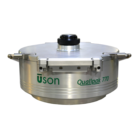
Section 2: Introduction Overview The Qualipak-770 is an easy-to-use leak testing fixture used with Uson’s Optima vT Leak Tester to perform seal integrity and leak testing on packages/parts for the food, medical, and pharmaceutical industries. See Figure 1. The Qualipak-770 Packaging Test System instructions are outlined in two manuals: •... -
Page 7: Specifications
During the test, the part under test is subjected to a vacuum supplied by the Uson Leak Tester. The vacuum level is regulated by the Optima Leak Tester, and during the test, the Qualipak-770 feeds back a signal from a load cell to the Uson Leak Tester. -
Page 8: Getting Started
Perform the following steps to get your system ready to use: 1. Unpack the Optima Package Test Fixture and the Optima vT Leak Tester. 2. Turn the QUALIPAK-770 upside-down and place on a sturdy workbench. Then remove the fixture’s bracket by unscrewing its 2 screws. See Figures 2 & 3. - Page 9 Figure 3:Package Tester Connections Completed 6. Turn the fixture upright, and then remove the two transit screws. See Figure 4. Figure 4: Transit Screws 7. Connect power supply to the Optima vT’s 24vdc input. See Figure 5. The systems power supply must be connected to an earthed (grounded) power supply of 90 - 260V, 50 - 60Hz.
- Page 10 Figure 5: P: Optima vT Power/Air Connections - Side View 13. Connect serial communication and power cables to the printer (optional). See Figure 6. Figure 6:Serial Communications 14. Switch the program/run key to run (key in horizontal position). See Figure 7. Figure 7: Optima vT Interface Mode Key 8 ...
-
Page 11: System Test/Chamber Seal Test
System Test/Chamber Seal Test Follow these steps to perform a system test/chamber seal test: 1. On the Optima vT, enter the dashboard screen by selecting Run Mode Dashboard (refer to Optima vT manual). See Figure 8. 2. Select Program 112 (chamber seal test) from drop down menu. Figure 8: Dashboard Screen 3. - Page 12 4. Run test to ensure system integrity. Press Start button (if the start button is not on the dashboard, use start on remote box). Allow test cycle to complete its 5 steps: Fill, Isolate, Stabilize, test and Exhaust (see Figure 10). The result of this test should be less than 0.3 mbar.
-
Page 13: Section 3: Operation
Section 3: Operation Testing Principle The Optima Q770 is based on the same test principle as the early Q700 range for flexible package testing. However, the parameters are now unrestricted, and can be programmed to suit your specific application. The test principle is a vacuum is applied to the chamber, which encourages the pack to inflate. -
Page 14: Testing
Testing To Perform a Test: 1. Select correct program for package to be tested from. See “Pre-programmed Tests” later in this section. 2. Insert package into cavity, ensuring the pack is central and is not hanging over the cavity. Ensure pack is not folded. See Figure 12. Figure 12: Package Testing: Insert package 3. -
Page 15: Pre- Programmed Tests
• Programs 101, 102, 103: Designated for calibration of the sensors; cannot be seen in run mode. Recommended calibration only be performed by Uson trained engineers; errors could seriously affect results integrity. -
Page 16: Programming A New Test
Programming a New Test The Optima has a pre-configured test for a basis to create new tests from. This is programed into position 90 and is called “Master Program”. It is recommended to clone program 90 into a new position before editing. To do this: 1. - Page 17 Auto zero pressure: Zeros the pressure sensor before the test start, taking away any ambient pressure changes, which may affect the test. The pre-set limits are -68 to +68. If the instrument starts failing during this process, there may be a fault in the system, which requires checking.
-
Page 18: Sensors Tab
Stabilize measure right force: Described for “Stabilize measure 2”. Measure left: Measures the difference in force between the start of the measure step and the end of the measure step. If the force decay is larger than the limit, the pack will be read as a reject. -
Page 19: Outputs Tab
Outputs Tab Select the Outputs Tab (Figure 18) to enter the Outputs screen. This screen is used to select outputs to the valves and LEDs required for each step. S-CMD are used for turning on/off valves. Acc/Rej are assigned outputs to turn on for corresponding accept/reject results. -
Page 20: Step Limits Tab
Step Limits Tab Select the Step limits tab (Figure 20) to enter the Step Limits screen. Step limits are parameters/logic each step must fall within to pass or fail a step. If the step logic is not achieved, a fail/reject is given before moving to the next step. Each step must have a sensor selected to examine for a pass/fail. -
Page 21: Download To Tcu
Download to TCU Once all the steps have been programmed, select the Test tab (Figure 22), then select Download to TCU. For the “Test hold on reject” option, the operator will need to acknowledge the reject by pressing the red reject button. Once all programming has been completed, turn the key to Run (horizontal position) to start testing. -
Page 22: Challenge Test
Challenge tests are pre-programed tests (Program 110 & Program 111) for checking the unit’s performance against a known calibrated standard. You will need the Uson challenge unit and a calibrated micron leak. Standard programs with the standard results use a force of 10,000 grams. The program can be modified so the parameters more closely match the production setup, but the limits would also need adjusting after trials. - Page 23 Figure 24: Inserting Micron Leak Cartridge 4. Place the infill into the corresponding program side (110, left; 111, right). See Figure 25. Figure 25:Challenge Test – Insert Infill 5. Close lid, then press Start. After testing is complete, check that results match those in Table 1.
-
Page 24: Lid Adjustment
Lid adjustment Lid adjustment is only required if the infills have changed, or if new infills have been fitted. To Perform a Lid Adjustment 1. Select Lid Adjust (Program 109) from Optima vT interface: Run Mode > Dashboard. See Figure 26. Figure 26: Lid Adjustment Software Screen 2. - Page 25 4. Then turn center screw clockwise until sensor X2 & X3 start to increase in force (grams). Note if the sensors start to increase within the first half turn, repeat step 2, as the pressure plate was too low. 5.
-
Page 26: Section 4: Maintenance
Section 4: Maintenance Routine Maintenance To keep the system in good working order, the following routine maintenance schedule should be stringently followed. WARNING TO AVOID INJURY, ENSURE THE SYSTEM IS SHUT DOWN, AND THE POWER AND AIR SUPPLIES ARE TURNED OFF BEFORE ATTEMPTING ANY MAINTENANCE OR FAULT FINDING ... -
Page 27: Cleaning
• Check calibration of the transducers. This can be carried out by Uson service engineers. It is advisable to arrange a service contract so that calibration checks are carried out automatically by an engineer. Contact the service manager at Uson Ltd.
Need help?
Do you have a question about the Qualipak-770 and is the answer not in the manual?
Questions and answers