Table of Contents
Advertisement
Advertisement
Table of Contents

Subscribe to Our Youtube Channel
Related Manuals for Uson sprint iq


Summary of Contents for Uson sprint iq
- Page 1 Owner’s Guide...
- Page 2 Uson has made every attempt to completely describe the operation of the tester. Uson shall not be liable for technical or editorial errors or omissions. © Copyright 2007 Uson L.P.
-
Page 3: Table Of Contents
1.1.2: Electrical Hazards .............4 1.1.3: General Safety Issues ..........4 Chapter 2: Quick Start ........5 2.1: Fast-Track Setup ..............5 2.1.1: Sprint iQ Requires Clean Dry Air ......6 2.2: Front Panel Features ............7 2.2.1: Pass/Fail Lights ............9 2.2.2: Back Panel Components .........10 2.2.3: Connecting Power ...........11... - Page 4 Run Mode Options Menu ...........24 Program Mode Menu ..........32 Chapter 4: Programming......... 49 4.1: Introduction ..............49 4.1.1: Decay Testing ............50 Decay Test Parameters ..........53 Test Pressure ...............53 Pressure Error .............54 Timers in Decay Tests ..........55 Delta Pressure .............57 Pressure Change Calc. (Leak Rate) ......59 Pneumatic Signal/Noise Ratio ........60 4.1.2: Back-Pressure Flow Test ........61 4.1.3: Occlusion (Blockage) Test ........64...
-
Page 5: Chapter 1: Safety
However, the following hazards of working with pressurized systems should be given serious consideration before operating the Sprint iQ: • High-pressure pneumatic air systems are exponentially more hazardous as the pressure increases, or as the volume of a system increases. Testing equipment subjected to consistently high-pressure ranges has an 1.Jackson, Charles N., Jr., Sherlock, Charles N., technical editors, and Moore,... -
Page 6: 2: Electrical Hazards
Failure to do so may be hazardous and can cause damage to the equipment. 1.1.3 General Safety Issues Perform operations, maintenance, or troubleshooting procedures only after reading and comprehending all manuals and materials supplied with the Sprint iQ. Safety... -
Page 7: Chapter 2: Quick Start
2.1 Fast-Track Setup Connect clean, dry supply air. Connect peripheral devices, if any. Connect the power supply and turn on Sprint iQ. Turn the connector’s collar until it is finger-tight to ensure a good connection. Use the back panel switch to turn on the Sprint iQ. -
Page 8: 1: Sprint Iq Requires Clean Dry Air
2.1.1 Sprint iQ Requires Clean Dry Air Before connecting air (or other gas) to Sprint iQ, make certain the supply air is clean and dry and pressure doesn’t exceed the maximum input listed on the rear panel. Water vapor, particulates, and excessive pressure can damage Sprint iQ’s internal components and affect product testing... -
Page 9: Front Panel Features
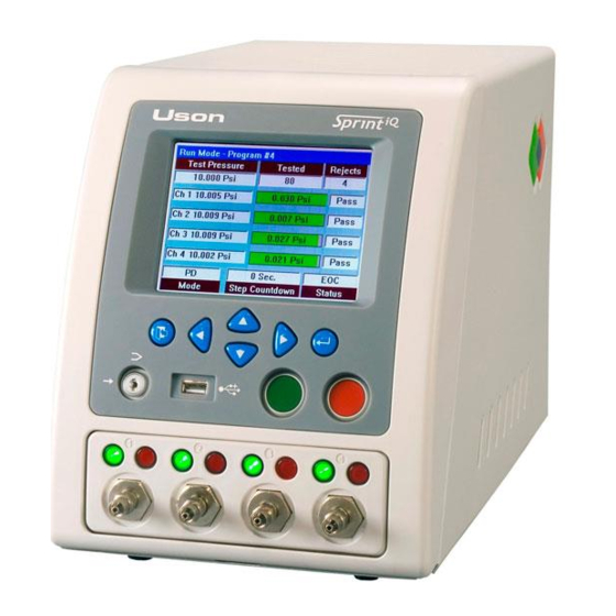
The front panel has an LCD display, keypad, Lockout keyswitch, USB port, and Stop and Start buttons. Display. The Sprint iQ has a 5.7" diagonal 320 x 240 color graphic liquid crystal display (LCD) with backlight. Keypad. The keypad has 6 keys: •... - Page 10 Lockout Keyswitch. Sprint iQ is in Run mode when the keyswitch is vertical. Turn the keyswitch counter-clockwise to the horizontal position to enter Program mode. The keyswitch in illustration below is in the vertical position.
-
Page 11: 1: Pass/Fail Lights
Repeated failures can indicate Sprint iQ or external fixtures have set-up problems. If a fail light turns on during a test, the operator can read the status box on the run display to see why the test was unsuccessful. -
Page 12: 2: Back Panel Components
2.2.2 Back Panel Components Pressure Regulator 1 (if ordered) Pressure Regulator 2 (if ordered) Coupling Ports (number varies with tester configuration) Fuse Power Switch Needle Valve (depends on configuration) Power Supply Connector Air Supply Ethernet Port (Optional) Connection Digital I/O #2 USB 2.0 Ports: (Optional) One Type A and One Type B... -
Page 13: 3: Connecting Power
2. Referring to the figure below, connect the AC power cord to the power supply. (The type of power cord supplied with Sprint iQ will vary, depending on the country.) 3. Attach the DC output power cord to the rear panel of... -
Page 14: 4: Switch-On The Tester
Run Mode display. 2.2.5 Run Mode Display Overview Sprint iQ shows the Run Mode display during all test cycles in every test mode. If multiple programs are linked, Sprint iQ shows the run display for the program currently running. - Page 15 The right column shows the pass/fail status information for the last test completed on that channel. Mode Box. The testing mode is shown in this box. Sprint iQ can operate in many modes such as pressure decay (P Decay), flow, burst, etc.
-
Page 16: 6: Mode Box Messages
2.2.6 Mode Box Messages Mode Box Display The test mode is shown in the Mode Box . If Sprint is set to run linked tests, the Mode Box shows the first test type in a series. Selected TestMode Box Display Back P Back Pressure Back P Rate... -
Page 17: 7: Status Box Messages
2.2.7 Status Box Messages The status box on Sprint iQ’s run display shows information before, during, and after a test. Three kinds of facts are displayed in the status box-test type set to run, test phase, and results of the completed test. -
Page 18: 8: Test Parameters
When Test Parameters are Available If existing test values are at hand, begin by simply entering those values into the Sprint iQ. Once all values are set correctly, the Sprint iQ is ready for fine tuning. When Test Parameters are not Available... - Page 19 Setting Test Time As test times are developed, keep in mind the size and material of parts to be tested. Parts that are both small and rigid typically require short test times. Parts that are both large and flexible generally require longer test times.
-
Page 20: Fine Tuning
2.2.9 Put Sprint iQ to Work When everything is programmed and checked out, you’re ready to put Sprint iQ to work and start testing products. A few tips: • Explain controls and run display messages to operators. • Keep external connections to the product under test as straight, rigid, and direct as possible. -
Page 21: 10: In Case Of Trouble
• Is the power supply connected to the back panel and is it receiving power (the power supply’s green light is lit)? • Is supply air connected to Sprint iQ? • Is the supply air clean and dry? Air that contains moisture, oil, or hard particulate will damage Sprint iQ. -
Page 22: 11: Start Options
2.2.11 Start Options The Sprint iQ has options that modify the way it accepts the start input. These options are useful for integrating the Sprint iQ with fixtures that seal on the test part. Start Options are first categorized as being Local (Front Panel) or Remote (digital inputs on the back panel). - Page 23 Fixture Lid Start The Remote Start input starts the test cycle. Remote Start must continue to be asserted throughout the test cycle, otherwise, its release aborts the test. Also, Remote Stop can optionally be used to abort the test cycle at any time. The Remote Start Enable input is not used for this start policy and is ignored.
- Page 24 Quick Start...
-
Page 25: Chapter 3: Menus
This simple menu which is accessed from Run Mode is discussed beginning on the following page. Remember that Sprint iQ is available in many configurations. Therefore, each tester may not display every menu item shown in the following pages. -
Page 26: Run Mode Options Menu
3.0.2.1 Run Mode Options Menu Press the Enter button while at the run screen to access the Run Mode Options Menu. Run Mode Options Menu 1. Program Selection 2. Print Menu 3. View Menu 4. Results Menu 5. Verification Function Use the Up and Down keys to highlight the option name and press Enter to select. - Page 27 The number of digits to enter may vary from what is shown in this manual as it will sometimes depend on the type of units or number formats chosen in setup. This symbol shows entries that cycle repeatedly through the range of values when changing them with the Left and Right keys.
- Page 28 Run Mode Options Menu Remember that Sprint iQ is available in many configurations. Therefore, each tester may not display every menu item shown in the following pages. 1. Program Selection This is the top-level menu. Run Mode Options Menu 1. Program Selection 2.
- Page 29 The remaining items are listed below. To help with staying oriented in the list, the opening menu and any sub-menus are shown. Always bear in mind that not all functions and items shown here may be available on every Sprint iQ model. 2. Print Menu Menus...
- Page 30 1. Program Selection ➩ Parameter Editor ➜ to 100 (Program number) 2. Print Program 3. Print Program Header 4. Print Setup 5. Print Statistics 6. Print Results 3. View Menu 1. Display format 2. Sensor Type 3. Channel 4. Phase 4.
- Page 31 Profile Options Menu 1. Channel Selection ➩ Parameter Editor ➜ ➜ 2. Sensor Function ➩ Parameter Editor ➜ Gauge Pressure Flow 3. Max Range ➩ Parameter Editor ➜ +00.000 to 99.999 4. Min Range ➩ Parameter Editor ➜ +00.000 to 99.999 2.
- Page 32 Histogram Option Menu Histogram Option Menu 1. Channel Selection 2. Program Selection 3. Number of Bins 4. Max Range 0.000 Psi 5. Min Range 0.000 Psi 1. Channel Selection ➩ Parameter Editor ➜ ➜ ➜ 2. Program Selection ➩ Parameter Editor ➜...
- Page 33 Trend Graph Options Menu Trend Graph Options Menu 1. Channel Selection 2. Program Selection 3. Max Range 0.000 Psi 4. Min Range 0.000 Psi 1. Channel Selection ➩ Parameter Editor ➜ ➜ ➜ 2. Program Selection ➩ Parameter Editor ➜ to 100 4.
-
Page 34: Program Mode Menu
3.0.2.2 Program Mode Menu Turn the Lockout Keyswitch to the horizontal position to go to the Program Mode Menu. The ability to use the menu item will vary depending on the configuration of the particular tester. Program Mode 1. Test Parameter Menu 2. - Page 35 Test Parameter Menu Test Parameter Menu 1. Program Number 2. Program Name 3. Test Type Pressure Decay 4. Channel Selection 5. Sample Interval 0.1s 6. Sample Channel 7. Couple Menu 8. Fast Fill Menu 9. Regulator Selection Test 1. Program Number ➩...
- Page 36 5. Sample Interval ➩ Parameter Editor ➜ ➜ 0.1sec to 1.0 sec 6. Sample Channel ➩ Parameter Editor 7. Couple Menu NOTE: The number of couple outputs varies with tester configuration. Couple Menu 1. Program Selection 2. Couple Output 3. Couple Control 4.
- Page 37 5. Occlusion Release ➩ Parameter Editor ➜ 6. Hold On Reject ➩ Parameter Editor ➜ 8. Fast Fill Menu Fast Fill Menu 1. Program Selection 2. Pressure 10.000 Psi 3. Pressure Error 10.000 Psi 4. Fill Time 0.0s 5. Vent Time 0.0s 1.
- Page 38 5. Vent Time ➩ Parameter Editor ➜ 00.0 to 99.9 9. Regulator Selection ➩ Parameter Editor ➜ Test Vacuum 10. Test Pressure ➩ Parameter Editor ➜ 00.000 to 99.999 11. Pressure Error ➩ Parameter Editor ➜ 00.000 to 99.999 12. Ramp Start 13.
- Page 39 1. Program Selection NOTE: Must select a Pressure Decay Rate or Vacuum Decay Rate program to enable the menu. 2. Leak Compensation ➩ Parameter Editor ➜ Enabled Disabled 3. Perform Leak Compensation Test 4. Leakrate Format ➩ Parameter Editor (cycle through decimal formats) 5.
- Page 40 12. Pneumatic S/N Ratio (Displays as 99999 if Comp Value is set to zero). 13. Verification Control ➩ Parameter Editor ➜ Enabled Disabled 14. Verification Tolerance ➩ Parameter Editor ➜ to 50% 15. Verification Interval ➩ Parameter Editor ➜ 0 hr to 23 hr 20.
- Page 41 5. Reject Minimum ➩ Parameter Editor ➜ +00.000 to 99.999 6. Pass Criteria ➩ Parameter Editor ➜ ➜ In Band Above Reject Max Below Reject 7. Event Limit ➩ Parameter Editor ➜ 0.0000 to 9.9999 21. Jump Menu Jump Menu 1.
- Page 42 4. On Pass Next Program ➩ Parameter Editor ➜ ➜ to 100 5. On Reject Pause Time ➩ Parameter Editor ➜ 00.0 to 99.9 6. On Reject Automatic Advance ➩ Parameter Editor ➜ 7. On Reject Next Program ➩ Parameter Editor ➜...
- Page 43 Data Menu 1. Clear All Counters 2. Audit Menu 3. Import Menu 4. Export Menu Audit Menu Audit Menu 1. Audit Printout Disabled 1. Audit Printout ➩ Parameter Editor ➜ Disabled Enabled Statistics Menu Menus...
- Page 44 Import Menu Import Menu 1. Import From Device 2. Data Selected Single Program 3. Program Selected 4. Import Data 1. Import from device ➩ Parameter Editor 2. Data Selected ➩ Parameter Editor ➜ ➜ ➜ Single program Test Channel Setup ➜...
- Page 45 Export Menu Export Menu 1. Export Device 2. Data Selected Single Program 3. Program Selected 4. Export Data 1. Export to device ➩ Parameter Editor 2. Data Selected ➩ Parameter Editor ➜ ➜ ➜ Single program Test channel Set up ➜...
- Page 46 ➜ None Hold on Reject Hold on Pass Infinite Fill 4. Remote Start This selection is not available unless Remote Start has been enabled in Remote Control, Accessory Menu by Uson. ➩ Parameter Editor ➜ ➜ ➜ ➜ Conventional Fixture...
- Page 47 5. Program Selection ➩ Parameter Editor ➜ ➜ Front Panel Remote Port Program Mode 6. Program Input Decode ➩ Parameter Editor Binary 7. Time ➩ Parameter Editor (Time [hh:mm:ss]) Hour:Minutes:Seconds 8. Date ➩ Parameter Editor (Date [mm/dd/yyy]) Month:Day:Year 9. Language ➩...
- Page 48 Hardware Menu Hardware Menu 1. Calibration Menu 2. Serial Port Menu 3. Printer 4. Network Menu 1. Calibration Menu Calibration Menu 1. Sensor Function 2. Sensor Input 3. Sensor Range 4. Channel Selection 5. Perform Calibration 6. Set Factory Defaults 1.
- Page 49 5. Perform Calibration 1. Save Greyed out until calibration has been performed. 2. Target Point 3. Regulator Setting 4 Target Point Calibrated 5. Sensor 1 6 Sensor 2 7. Sensor 3 8. Sensor 4 6. Set Factory Defaults 2. Serial Port Menu 3.
- Page 50 Menus...
-
Page 51: Chapter 4: Programming
Programming Chapter 4 4.1 Introduction Sprint iQ ships with several factory-installed programs with default parameters. These may be kept or changed by the user to suit the actual testing requirements. Please note that not all test types are available in every tester. -
Page 52: 1: Decay Testing
1. The part to be tested [TP] is attached to the test port and the test is started. 2. Sprint iQ pressurizes the part with pressure [+P] to the desired test pressure set by the pressure regulator [R1] by opening valves [V1] and [V2] during the Fill step. - Page 53 6. At the end of Test step, pressure trapped in the part is vented to atmosphere through [V1] by opening [V2] during the Vent step, and Sprint iQ is ready to make the next test. Vacuum Decay Testing Sprint iQ can be equipped with either: •...
- Page 54 1 liter) and/or increased negative pressure (> 25 inHg/ 12.5 psig). Incorporating a negative pressure sensor, vacuum source (typically), regulator, valves, and logic control, the Sprint iQ handles the task of vacuum testing within a small enclosure. Most applications can be conducted using Sprint iQ’s pneumatically-driven internal venturi vacuum source.
-
Page 55: Decay Test Parameters
If the regulator is adjusted or inadvertently moved after the target test pressure is set, Sprint iQ stops the test and shows an error in the run display. The preset test pressure should be very close to the actual pressure from which the product starts to drop. -
Page 56: Pressure Error
In a pressure decay test, the pressure error is set as an equal plus and minus tolerance around a nominal test pressure value. Enter the number in pressure units and Sprint iQ sets both the high and low pressure error values. Sprint iQ monitors pressure error during the fill and stabilization phases of a pressure decay leak test. -
Page 57: Timers In Decay Tests
4.1.1.4 Timers in Decay Tests Couple Time Couple time is used as a delay causing Sprint iQ to wait for a preset period after start is activated and before Sprint iQ supplies air to the part to be tested. Couple time can be used in either a manual or automated operation. - Page 58 The instant the test enters test phase, Sprint iQ takes the first pressure reading and stores this value P1. At the end of test phase, Sprint iQ takes a final reading and holds this value as P2. The difference between P1 and P2 is the total test pressure loss over the test time.
-
Page 59: Delta Pressure
Sprint iQ uses the pressure drop to compare to the maximum allowable loss (known as the reject maximum) to decide whether a product is accepted as good or rejected as bad. - Page 60 A gross leak is detected when pressure drops below the negative pressure error during stabilization time. When a gross leak is detected, Sprint iQ stops the test and shows Gross in the status box on the run display. A gross leak is generally caused by a product having a severe defect or because external fixtures are not sealing the product.
-
Page 61: Pressure Change Calc. (Leak Rate)
4.1.1.6 Pressure Change Calc. (Leak Rate) In tests such as Pressure Decay Rate, Sprint iQ calculates the leak rate from the pressure change over time using values derived from the following formulae. Variable Definitions for the Calculations: CalRate = Leak Master Leak Value (user-entered value) -
Page 62: Pneumatic Signal/Noise Ratio
4.1.1.7 Pneumatic Signal/Noise Ratio The larger the PSN Ratio, which is the Cal Value divided by the Comp Value, the more repeatable the test will be. The PSN Ratio can be in the range of 0.2 to 0.25 if +/- 10% test repeatability is sufficient. -
Page 63: 2: Back-Pressure Flow Test
An occlusion test, discussed on page 64, is typically used on smaller parts Sprint iQ testers can conduct back-pressure flow testing by using the same basic pneumatic circuit employed in pressure decay. The programming is the only difference since the part is not expected to maintain pressure. - Page 64 [R1] by opening valves [V1] and [V2] throughout the test. 3. At the end of Test step, Sprint iQ looks for a specific back-pressure using its pressure sensor [PS]. 4. If the measured back-pressure during the Test step is outside accept/reject setpoints entered into the test program, the Sprint iQ’s display shows why the part...
- Page 65 The figure to the right shows a typical back- pressure flow test in which the part passes the evaluation. In this example, the residual back-pressure seen at the part’s inlet (while the outlet is vented to atmosphere) was within the established reject minimum and reject maximum limits, indicating that the passage was the correct size.
-
Page 66: 3: Occlusion (Blockage) Test
Thanks to the commonality of test circuits, it is possible to conduct pressure decay tests followed by occlusion tests. This is easy to accomplish with Sprint iQ’s program linking ability. Programming... - Page 67 Sprint iQ starts taking pressure drop readings. For large flow rates stabilization time is not needed and can be set to zero. 5. At the end of stabilization time, Sprint iQ starts looking for a drop in pressure from the stabilized pressure. Programming...
- Page 68 Sprint iQ goes into test phase only if test pressure is within the pressure error tolerance. 6. During test time, the coupling is released and the test part is opened to atmosphere. Sprint iQ compares the pressure drop to the set limits. IF the pressure decay (or pressure loss) is greater than the reject minimum at the end of test time, the pass indicator lights up.
- Page 69 Sprint iQ goes into test phase only if test pressure is within the pressure error tolerance by the end of the fill phase.
- Page 70 8. At the end of all linked tests, the operator (or automated machinery) removes the product and Sprint iQ is ready to begin the next test. The product is pressurized during fill time, and the pressure is not able to rise above the pressure error limit.
-
Page 71: 4: Flow Test
A flow test continuously supplies air to a product under test and measures the amount of air flowing through the product and going to atmosphere. In a flow test, Sprint iQ uses at least one mass flow sensor to measure the air flow, and a pressure transducer to monitor the air pressure. - Page 72 • Next Program Protect the Flow Sensor Do NOT run a flow test unless product is attached to Sprint iQ's test port. Without this restriction, the high flow rate could damage the flow sensor. Pressure Error in a Flow Test Pressure error is used to make sure pressure is at the target level to perform a flow test.
-
Page 73: Leak Test Using Flow
If the air flow measured by Sprint iQ’s mass flow sensor is below the minimum setpoint at the end of test phase, Sprint iQ turns on the reject light and shows LOW in the status box on the run display. - Page 74 Protect the Flow Sensor Do NOT run a flow test unless product is attached to Sprint iQ's test port. Without this restriction, the high flow rate could damage the flow sensor. In a leak test using flow, you have the option of using fill time or going straight to test phase.
-
Page 75: Flow Sensor Over Pressure Limits
4.1.4.3 Flow Sensor Over Pressure Limits The flow sensor in the Sprint iQ can be damaged by too much pressure. The Sprint iQ automatically monitors the pressure and will stop a flow test if the pressure is too high. The below table shows the maximum pressure associated with each flow range. - Page 76 A burst test is built around two test conditions: 1. Peak Pressure (P) Peak Pressure is a constantly updated value before the burst. Sprint iQ uses the peak pressure reading as the starting point to measure the event value. After the event the final peak value is compared to the minimum and maximum burst setpoints to decide whether the product is accepted or rejected.
- Page 77 The fail light turns on. If product fails to reach a peak pressure above the maximum burst setpoints before the end of the test phase, Sprint iQ stops the test and shows NoBurst in the status box on the run display.
-
Page 78: 6: Creep Test
4.1.7 Crack Test Crack testing is a test in which the Sprint iQ is used to detect a slight opening or change in pressure. Crack testing is used in devices such as valves intended to open a certain pressure range. - Page 79 Being upstream from the product, the normal sensor is subjected to constant makeup air. To test products that open slowly or merely “weep,” Uson can provide a separate sensor used downstream from the cracking device to detect very slight pressure or flow changes.
- Page 80 The Crack Event For a crack test, Sprint iQ is equipped with two sensors. The standard transducer measures the pressure rise being feed to the test part, on the upstream side. The second sensor is the downstream sensor. The crack event is a change in pressure or flow on the downstream side of the test part.
-
Page 81: 8: Pass/Reject Jumps
4.1.8 Pass/Reject Jumps The Sprint iQ tester has additional control to link the test programs together based on either a pass or reject condition. This feature also adds the ability to pause the test sequence between linked test programs. Jump Menu 1. -
Page 82: 9: Timers
4.1.9 Timers Timers are set in tenths of seconds, and each timer can be set to a maximum of 99.9 seconds. Timers are adjustable for pressure decay, flow, and burst testing. Timers for each test type have identical functions for each test mode, yet the number of possible timers may vary with each test type as seen in this listing: Timers Used in Decay &... -
Page 83: Chapter 5: Reference
Reference Chapter 5 5.0.1 General Specifications Display: 5.7” Diagonal 320 x 240 Color Graphic Backlit LCD Languages: English (UK and US), Spanish, German (user selectable). Custom languages also available Program/Setup Storage: 100 (99 alpha-numeric namable & 1 diagnostic) Test Channels Available: 1, 2, 3 or 4 (sequential or concurrent) Pressure Ranges Available: 3, 5, 10, 15, 30, 50, 100, 200, 300 and 500 psig. - Page 84 Mass Flow Ranges Available: 10, 50, 200, 500, (15 psig max) 5000, 20000 sccm (60 psig max). Custom ranges also available Maximum Mass Flow Display Resolution: 0.01 sccm (range dependant) Mass Flow Sensor Repeatability: 0.5% of Full Scale Mass Flow Units of Measure: sccs, sccm, scch, smls, smlm, smlh, sls, slm, slh (user selectable) Base Unit Dimensions:...
-
Page 85: 2: Standard Features
5.0.2 Standard Features • High Performance 24 Bit Analog to Digital (A-D) Converter • Leak Rate in sccm or )P (pressure change) • True Volumetric Calibration Capable (Compensation & Calibration) • Low System Volume for Maximum Sensitivity • Dual USB Communication Ports (Front & Rear) •... -
Page 86: 3: Optional Features
5.0.3 Optional Features • Additional Expanded I/O: 8 Configurable Inputs16 Configurable Outputs • Additional Regulator • Bar Code Reader • Continuous Fill • Coupling Ports (up to 8 and can accommodate up to 4 four- way valves) • Data Statistics & Histograms •... -
Page 87: 4: Digital I/O Pin Assignments
5.0.4 Digital I/O Pin Assignments Digital I/O is an Function Pin No. optional feature. The START (+) connector may be START ENABLE (+) found in the location RESET (+) shown on page 10. BCD 0 (+) BCD 1 (+) The inputs are BCD 2 (+) single-ended. -
Page 88: 5: Converting Pressure To Flow Rate
LCD. The pressure drop is the delta pressure (P) in the formula. Delta time (t) is the test timer value set in Sprint iQ’s pressure decay program (provided the test passes). Because this timer is set in seconds, merely divide by 60 to get the delta time in minutes. -
Page 89: 6: Concepts Applicable To Testing
5.0.6 Concepts Applicable to Testing Pressure In physics, pressure is a force measured in terms of its distribution over an area of an opposing force. This is expressed as force (F) divided by unit area (A) of the surface area to which the force is applied. Air pressure most commonly refers to a force exerted uniformly in all directions. - Page 90 of the total molecules in the atmosphere. Diatomic oxygen represents nearly 21%. The inert noble gas, argon, accounts for about 0.9%, and the remaining 0.1% is composed of many trace gases, the most significant being carbon dioxide and water vapor. Carbon dioxide makes up only 325 parts per million of the atmosphere by volume.
- Page 91 Sprint IQ measures true air flow in units standardized to 29.92 inHg (14.68 psi) at 20 degrees C. Although the Sprint IQ’s measurements are accurate and traceable to NIST standards, flow readings could be different if the tester is used at drastically different altitudes.
- Page 92 Gas vs. Liquid Unlike liquids, gases cannot be poured from one open container into another, but they deform under shear stress just the same. Because shear stresses result from relative motion, stresses are equivalent whether the fluid flows past a stationary object or the object moves through the fluid.
- Page 93 Laminar vs. Turbulent Flow When flow velocity increases, the flow becomes unstable, and changes from laminar to turbulent flow. In turbulent flow, gas particles start moving in highly irregular and difficult-to- predict paths. Eddies form and transfer momentum over distances varying from a few millimeters, as in controlled laboratory experiments, to several meters, as in a large room or other structure.
- Page 94 idea to invent the hydraulic press. Pascal’s principle is often used in devices that multiply an applied force and transmit it to a point of application. Examples include the hydraulic jack, and the pneumatic cylinder. Gas Laws The actions of gases under varying conditions of temperature, pressure, and volume can be described and predicted by a set of equations, or gas Laws.
- Page 95 is the volume of the gas, T is the temperature on the absolute scale, and the constant depends on the pressure and the amount of gas present. In 1802, Joseph Gay-Lussac played around with the relationship between pressure and temperature and came up with an equation a lot like Charles’s Law: P/T = Constant.
- Page 96 Adiabatic Process (ad-ee-uh-bat-ik) Adiabatic compression and expansion are thermodynamic processes in which the pressure of a gas is increased or decreased without any exchange of heat energy with the surroundings. Any process that occurs without heat transfer is called an adiabatic process. The adiabatic compression or expansion of a gas can occur if the gas is insulated from its surroundings or if the process takes place quickly enough to prevent any significant heat...
-
Page 97: 7: Terminology Reference
Standard bulkheads on the front have a #10 by 32 pitch machine thread. Burst Test: One of Sprint iQ’s possible operating modes in addition to pressure decay and flow. A burst test slowly fills a product through a flow valve set by users. After the burst, pressure rapidly drops to near zero. - Page 98 Cal Value: Cal Value = Pressure change during the leak test step with a calibrated leak master – the Comp Value. Calibration: Comparison of a device (such as Sprint iQ) to a standard that is in turn calibrated to an even more accurate standard.
- Page 99 Counters: Sprint iQ records the total number of tests performed (both pass and fail) and number of rejects (fail only). Running totals are displayed to operators in the tested and reject boxes on the run display. Counters may be cleared from the Program Mode Data Menu.
- Page 100 (vacuum). Event: The instant pressure drops below the event value during a burst or creep test. Sprint iQ monitors pressure during a burst test or creep test and holds the maximum pressure value measured before the event (pressure drop) occurred.
- Page 101 Flow Master: A measuring instrument or certified restrictor that can be connected to Sprint iQ as part of a flow calibration. The flow standard must have adequate accuracy, stability, and repeatability needed to calibrate Sprint iQ.
- Page 102 If Sprint iQ indicates a gross leak in good products, a larger pressure error value may be needed. This is often the case when testing large product or products constructed of flexible materials.
- Page 103 Jump: In the Test Parameter Menu use the Jump Menu to link programs in a variety of ways. Keypads: The six blue buttons on Sprint iQ’s front panel used to enter program values and other setup information. LCD: Abbreviation for liquid crystal display. Sprint iQ’s display is an LCD device that provides setup prompts, menu options, test results, and other system information.
- Page 104 (horizontal) position. Main Digital Readout: In the center of Sprint iQ’s run display screen, the main digital readout is visible when Sprint is in run condition. This readout shows the pressure and flow values during pressure decay, flow, and burst testing.
- Page 105 Sprint also shows the error in the status box on the run display. Pressure Regulator: The Sprint iQ can be configured to support up to 3 regulator inputs depending upon the model type and option configurations. (Also see “Electronic Programmable Regulator”...
- Page 106 external or internal vacuum supply or vacuum venturi controlled by a manual or electronic pressure regulator. Sensor 1 configuration will define the operating range of the regulated supply input. Auxiliary: The second regulated supply which is fitted as an option. This allows the user to select a second common manual regulated supply for the fast fill option or as an alternative test pressure for all test channels within a sequential tester and common regulator concurrent tester...
- Page 107 Pressure: The relative force of a compressed air or gas. Sprint iQ is generally configured to use PSIG, which is the force of compressed gas relative to barometric pressure. Pressure Transducer: An electro-mechanical device (also called a sensor) that converts pneumatic pressure into electrical signals.
- Page 108 Run: When the lockout key is in the vertical position, Sprint is in Run Mode. Sprint iQ is set to run when used in production testing. The only other keyswitch condition is Program Mode (lockout key in horizontal position).
- Page 109 Sprint iQ: In this guide, the word Sprint iQ refers to the base- model Sprint iQ air tester. Your particular tester will probably not have all the options explained in this owner’s guide.
- Page 110 Target: A pre-programmed number that Uson stores in firmware used to calibrate Sprint iQ’s pressure and flow sensors. The target value is matched to a pressure or flow standard to create a lookup table for sensor linearity adjustment.
- Page 111 Test pressure is set by adjusting the air regulator on the back of Sprint iQ. Test pressure can only be set if Sprint iQ has supply air connected and the output port is blocked with a leak-tight cap.
- Page 112 Sprint tester is dependant on the model and configuration. Vent: After Sprint iQ completes a decay test, a valve can be activated to open the product and Sprint’s internal test circuit to atmosphere. The action of releasing pressure to atmosphere is called vent.
-
Page 113: 8: Electronic Programmable Regulator
Also, because the regulator is programmed using Sprint iQ’s security key, it can supply different test pressures or ramp rates for each of Sprint iQ’s stored programs and no operator adjustment is needed (or possible) without possession of the security key. - Page 114 How it Works 1. Sprint iQ is set to Program mode. 2. In the Program setup screen, setup personnel digitally enter test pressure values using Sprint iQ’s normal programming methods. 3. Unique test pressures can be entered for each of Sprint iQ’s stored programs.
- Page 115 Ramp Rate Ramping is used in burst, crack and creep testing. Ramp Rate is an increase in pressure over time. Sprint iQ’s Electronic Programmable Regulator precisely controls the ramping pressure. Often, cycle time can be saved and burst or crack event...
- Page 116 45 pounds per square inch pressure then increase at a rate of 10 pounds per square inch every second. Reference...
- Page 117 Index Calibration Data ... . 96 Calibration Menu ..46, 96 abort ....16, 95 Channel number .
- Page 118 Date ..... . .45 Firmware version ... . 12 Decay ....49, 98 Fixture Lid Start .
- Page 119 Local Start Option ... 20 Lockout keyswitch . . 7, 8, 32, 102 I/O ..... . 101 LoCrack .
- Page 120 NIST ..... .84 Pressure ... . 87, 90, 105 NoBurst ....16, 75 Pressure Burst .
- Page 121 Reinitialize ....45 Setup Menu ....44 Reject Level ....105 Splash screen .
- Page 122 Timers ....80, 109 venturi vacuum generator ..51 Turbulent Flow ....91 Verification Function .
Need help?
Do you have a question about the sprint iq and is the answer not in the manual?
Questions and answers