Table of Contents
Advertisement
Quick Links
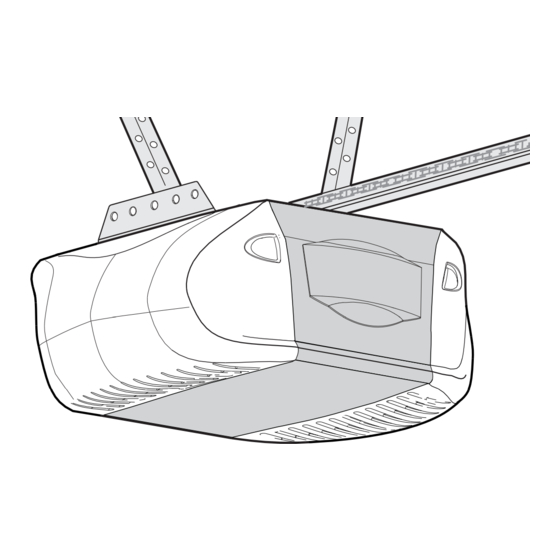
GARAGE DOOR OPENER
Model 3575
For Residential Use Only
Owner's Manual
■
Please read this manual and the enclosed safety materials carefully!
■
Fasten the manual near the garage door after installation.
■
The door WILL NOT CLOSE unless the Protector System
aligned.
■
Periodic checks of the opener are required to ensure safe operation.
■
The model number label is located on the left panel of your opener.
®
The Chamberlain Group, Inc.
845 Larch Avenue
Elmhurst, Illinois 60126-1196
www.liftmaster.com
®
is connected and properly
Advertisement
Table of Contents

Related Manuals for Chamberlain SECURITY+ Elite Series


Summary of Contents for Chamberlain SECURITY+ Elite Series
- Page 1 The Chamberlain Group, Inc. 845 Larch Avenue Elmhurst, Illinois 60126-1196 www.liftmaster.com ® GARAGE DOOR OPENER Model 3575 For Residential Use Only Owner’s Manual ■ Please read this manual and the enclosed safety materials carefully! ■ Fasten the manual near the garage door after installation.
-
Page 2: Table Of Contents
TABLE OF CONTENTS Introduction Operation 26-32 Safety symbol and signal word review ....2 Operation safety instructions ..... .26 Preparing your garage door . -
Page 3: Preparing Your Garage Door
Preparing your garage door WARNING Before you begin: To prevent possible SERIOUS INJURY or DEATH: • Disable locks. • ALWAYS call a trained door systems technician if garage CAUTION • Remove any ropes connected to garage door. door binds, sticks or is out of balance. An unbalanced garage door may not reverse when required. -
Page 4: Planning
Planning Identify the type and height of your garage door. Survey your garage area to see if any of the conditions below apply to your installation. Additional materials may be required. You may find it helpful to refer back to this page and the accompanying illustrations as you proceed with the installation of your opener. -
Page 5: Carton Inventory
Carton Inventory Your garage door opener is packaged in two cartons If anything is missing, carefully check the packing which contain the motor unit and all parts illustrated material. Parts may be stuck in the foam. Hardware for below. Accessories will depend on the model purchased. installation is also listed below. -
Page 6: Assembly
WARNING CAUTION ASSEMBLY STEP 1 Attach the T-Rail to the Motor Unit To avoid SERIOUS damage to garage door opener, use ONLY those bolts/fasteners mounted in the top of the opener. To avoid installation difficulties, do not run the garage door opener until instructed to do so. -
Page 7: Tighten The Chain
Figure 1 ASSEMBLY STEP 3 Lock Washer Outer Nut Tighten the Chain Inner Nut To Tighten Outer Nut • Spin the inner nut and lock washer down the trolley To Tighten threaded shaft, away from the trolley. Inner Nut • To tighten the chain, turn outer nut in the direction shown (Figure 1). -
Page 8: Determine The Header Bracket Location
Unfinished INSTALLATION STEP 1 Ceiling OPTIONAL CEILING Determine the Header Bracket MOUNT Location HEADER BRACKET Header Wall WARNING WARNING Vertical Centerline of Garage Door To prevent possible SERIOUS INJURY or DEATH: • Header bracket MUST be RIGIDLY fastened to structural Structural CAUTION WARNING... -
Page 9: Install The Header Bracket
INSTALLATION STEP 2 Install the Header Bracket Wall Mounting Holes You can attach the header bracket either to the wall above the garage door, or to the ceiling. Follow the instructions CEILING MOUNT ONLY The nail hole is for which will work best for your particular requirements. Do positioning only. -
Page 10: Attach The Rail To The Header Bracket
INSTALLATION STEP 3 Attach the Rail to the Header Bracket • Position the opener on the garage floor below the header bracket. Use packing material as a protective base. NOTE: If the door spring is in the way you’ll need help. -
Page 11: Position The Opener
WARNING CAUTION INSTALLATION STEP 4 Position the Opener To prevent damage to garage door, rest garage door opener rail on 2x4 placed on top section of door. Follow instructions which apply to your door type as illustrated. SECTIONAL DOOR OR ONE-PIECE DOOR WITH TRACK A 2x4 laid flat is convenient for setting an ideal door-to-rail distance. -
Page 12: Hang The Opener
WARNING INSTALLATION STEP 5 Hang the Opener To avoid possible SERIOUS INJURY from a falling garage door opener, fasten it SECURELY to structural supports of the CAUTION Three representative installations are shown. Yours may garage. Concrete anchors MUST be used if installing any be different. -
Page 13: Install The Control Console
WARNING WARNING CAUTION WARNING INSTALLATION STEP 6 Install the Control Console To prevent possible SERIOUS INJURY or DEATH from electrocution: Locate control console within sight of door, at a minimum • Be sure power is not connected BEFORE installing door height of 5' (1.5 m) where small children cannot reach, control. -
Page 14: Install The Light
WARNING CAUTION INSTALLATION STEP 7 Install the Light To prevent possible OVERHEATING of the endpanel or light socket: • Press the release tabs on both sides of lens. Gently • DO NOT use short neck or specialty light bulbs. rotate lens back and downward until the lens hinge is in •... -
Page 15: Electrical Requirements
WARNING WARNING INSTALLATION STEP 9 Electrical Requirements To prevent possible SERIOUS INJURY or DEATH from electrocution or fire: CAUTION WARNING To avoid installation difficulties, do not run the opener • Be sure power is not connected to the opener, and at this time. -
Page 16: Install The Protector System
WARNING INSTALLATION STEP 10 Install The Protector System ® Be sure power is not connected to the garage door opener BEFORE installing the safety reversing sensor. CAUTION The safety reversing sensor must be connected and To prevent SERIOUS INJURY or DEATH from a closing garage aligned correctly before the garage door opener will door: move in the down direction. - Page 17 INSTALLING THE BRACKETS Be sure power to the opener is disconnected. Install Figure 1 DOOR TRACK MOUNT (RIGHT SIDE) and align the brackets so the sensors will face each other across the garage door, with the beam no higher than 6" Door (15 cm) above the floor.
- Page 18 MOUNTING AND WIRING THE SAFETY REVERSING Figure 5 SENSORS Wing Nut • Slide a 1/4"-20x1/2" carriage bolt head into the slot on 1/4"-20 each sensor. Use wing nuts to fasten sensors to brackets, with lenses pointing toward each other across the door.
-
Page 19: Fasten The Door Bracket
WARNING CAUTION INSTALLATION STEP 11 Fasten the Door Bracket Fiberglass, aluminum or lightweight steel garage doors WILL REQUIRE reinforcement BEFORE installation of door bracket. Follow instructions which apply to your door type as Contact your door manufacturer for reinforcement kit. illustrated below or on the following page. - Page 20 ONE-PIECE DOORS Please read and comply with the warnings and reinforcement instructions on the previous page. They apply to one-piece doors also. • Center the door bracket on the top of the door, in line with the header bracket as shown. Mark either the left and right, or the top and bottom holes.
- Page 21 INSTALLATION STEP 12 Inner Trolley Connect Door Arm to Trolley Outer Trolley Follow instructions which apply to your door type as illustrated below and on the following page. SECTIONAL DOORS ONLY Clevis Pin 5/16"x1" Ring • Make sure garage door is fully closed. Pull the Fastener emergency release handle to disconnect the outer trolley from the inner trolley.
-
Page 22: Connect The Door Arm To The Trolley
ALL ONE-PIECE DOORS Door Ring Bracket 1. Assemble the door arm, Figure 4: Fastener Nuts • Fasten the straight and curved door arm sections Lock 5/16"-18 Washers together to the longest possible length (with a 2 or 3 5/16" hole overlap). Clevis Pin Straight 5/16"x1-1/4"... -
Page 23: Adjustment
WARNING ADJUSTMENT STEP 1 Adjust the UP and DOWN Travel Limits Without a properly installed safety reversal system, persons (particularly small children) could be SERIOUSLY INJURED or CAUTION Limit adjustment settings regulate the points at which the KILLED by a closing garage door. door will stop when moving up or down. -
Page 24: Adjust The Force
WARNING ADJUSTMENT STEP 2 Adjust the Force Without a properly installed safety reversal system, persons (particularly small children) could be SERIOUSLY INJURED or CAUTION Force adjustment controls are located on the right panel of KILLED by a closing garage door. the motor unit. -
Page 25: Test The Safety Reversal System
WARNING ADJUSTMENT STEP 3 Test the Safety Reversal System Without a properly installed safety reversal system, persons (particularly small children) could be SERIOUSLY INJURED or CAUTION KILLED by a closing garage door. TEST • Safety reversal system MUST be tested every month. •... -
Page 26: Operation
WARNING OPERATION IMPORTANT SAFETY INSTRUCTIONS WARNING To reduce the risk of SEVERE INJURY or DEATH: 1. READ AND FOLLOW ALL WARNINGS AND INSTRUCTIONS. 9. If one control (force or travel limits) is adjusted, the other control may also need adjustment. 2. -
Page 27: Using The Wall-Mounted Control Console
Using the Wall-Mounted (PROG) Learn Feature Control Console The control console is equipped with a PROG <LEARN> button to assist in learning remote controls to the unit. Press the PROG <LEARN> button once to initiate LEARN THE LCD MOTION DETECTING CONTROL CONSOLE mode and the display will show ‘Learn Remote Control - Press the push bar to Push... -
Page 28: Using The Remote Control
Using the Remote Control Troubleshooting NOTE: To activate the remote control functions, pull out PROBLEM SOLUTION the plastic pull tab protruding from the remote control housing. Check if proximity lighting is This remote control is equipped with a proximity lighting disabled by pressing a button. -
Page 29: To Open The Door Manually
To Open the Door Manually MAINTENANCE SCHEDULE Once a Month WARNING WARNING • Manually operate door. If it is unbalanced or binding, call a trained door systems technician. To prevent possible SERIOUS INJURY or DEATH from a falling • Check to be sure door opens and closes fully. Adjust garage door: CAUTION WARNING... -
Page 30: Having A Problem
HAVING A PROBLEM? Bell Wire 1. My door will not close and the light bulbs blink on my motor unit: The safety reversing sensor must be connected and aligned correctly before the garage door opener will move in the down direction. •... -
Page 31: Diagnostic Chart
Bell Wire Diagnostics Installed Located On Safety Reversing Motor Unit Sensor LED or Diagnostic Your garage door opener is programmed with self-diagnostic capabilities. The “Learn” button/diagnostic LED will "Learn" Safety Reversing Sensor flash a number of times then pause signifying it has found a Button potential issue. -
Page 32: Lcd Motion Detecting Control Console Messages
LCD Motion Detecting Control Console Messages The following messages are contained within the LCD Motion Detecting Control Console and may appear during the operations of the unit: Message Meaning: This message will appear if the Safety Reversing Sensors are out of alignment, if they are blocked or if the wiring is disconnected. -
Page 33: Programming
PROGRAMMING NOTICE: If this Security ✚ ® garage door opener is operated with a non-rolling code transmitter, the technical measure in the receiver of the garage door opener, which provides security against code-theft devices, will be circumvented. The owner of the copyright in the garage door opener does not authorize the purchaser or supplier of the non-rolling code transmitter to circumvent that technical measure. -
Page 34: To Add, Reprogram Or Change A Keyless Entry Pin
To Add, Reprogram or Change a Keyless Entry PIN NOTE: Your new Keyless Entry must be programmed to operate your garage door opener. USING THE “LEARN” BUTTON USING THE LCD CONTROL CONSOLE LO CK LI GH NOTE: This method requires two people if the Keyless Entry is already mounted outside the garage. -
Page 35: Repair Parts
REPAIR PARTS Rail Assembly Parts PART DESCRIPTION 4A1008 Master link kit 41A4813 Chain pulley bracket 41A3489 Complete trolley assembly 1707LM One-piece rail 41D3484 Full chain assembly 83A11-2 Rail grease Installation Parts KEY PART L O C DESCRIPTION L I G 398LM LCD motion detecting door control console 373P... -
Page 36: Motor Unit Assembly Parts
Motor Unit Assembly Parts (Down) LIMIT SWITCH ASSY. Brown Contact Wire Grey Wire Drive Gear Center Limit (Up) Yellow Contact Contact Wire PART PART DESCRIPTION DESCRIPTION 41A5615 Chain spreader 41A5633-12 Cover 41A5585-1 Gear and sprocket assembly 41A2818 Limit switch drive & retainer Complete with: Spring washer, 41D3452-2 Limit switch assembly... -
Page 37: Accessories
ACCESSORIES 1702LM Outside Quick Release: Designer Burled Walnut 3-Button 373W Required for a garage with NO Remote Control with Security✚ ® access door. Enables homeowner to open garage door manually from Includes visor clip. outside by disengaging trolley. 3-Button Security✚ Remote Control: ®... -
Page 38: Notes
NOTES... - Page 39 NOTES...
-
Page 40: Repair Parts And Service
LIFETIME MOTOR LIMITED WARRANTY The Chamberlain Group, Inc. (“Seller”) warrants to the first retail purchaser of this product, for the residence in which this product is originally installed, that it is free from defect in materials and/or workmanship for a period of five years from the date of purchase and that the motor is free from defect in materials and/or workmanship for the lifetime of the product.
Need help?
Do you have a question about the SECURITY+ Elite Series and is the answer not in the manual?
Questions and answers