Surefire BMS-100 Installation & Operation Manual
Hide thumbs
Also See for BMS-100:
- Installation & operation manual (40 pages) ,
- Installation & operation manual (43 pages)
Table of Contents
Advertisement
Quick Links
Advertisement
Table of Contents

Related Manuals for Surefire BMS-100


Summary of Contents for Surefire BMS-100
- Page 1 Proudly Made in INSTALLATION & OPERATIONS MANUAL the USA PROUDLY MADE IN THE USA...
-
Page 2: Table Of Contents
Table of Contents Table of Contents: Introduction: Certification and Warnings: Warranty and Return Policy: BMS-100 Description: SureFire Ignition Units: 10-11 SureFire Additional Components: 12-13 Installation Guide: 14-17 Specifications: Run Status, Alarm Out and Flame Strength: ... -
Page 3: Introduction
The BMS-100 is designed as a pilot maintainer for Flare, Combustor or Fire Tube applications within the Oil and Gas Industry. The BMS-100 is designed to operate with the FT Ignition units to provide optimal ignition. The controller’s display is designed to operate in ambient temperature from –40°F to 131°F, and is coated for corrosion resistance. -
Page 4: Certification And Warnings
Certifications and Warnings *WARNING* EXPLOSION HAZARD - SUBSTITUTION OF COMPONENTS MAY IMPAIR SUITABILITY FOR CLASS I, DIVISION 2, GROUPS C AND D, OR UNCLASSIFED APPLICATIONS; *MISE EN GARDE* RISQUE D’EXPLOSION - LA SUBSTITUTION DE COMPOSANTS PEUT ALTÉRER APTITUDE POUR LA CLASSE I, DIVISION 2, GROUPES C ET D OU DES APPLICATIONS DE UNCLASSIFED ;... -
Page 5: Warranty And Return Policy
If the product is deemed under warranty by SureFire, then the shipping cost incurred by shipping the product from SureFire to the customer will be at the expense of SureFire. If the product is deemed non-warranty by SureFire, then the shipping cost incurred by shipping the product from... -
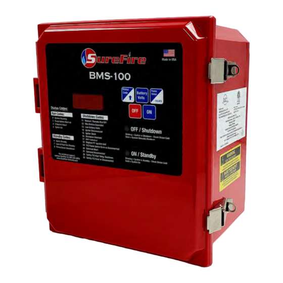
Page 6: Bms-100 Description
Enclosure: The SureFire BMS-100 system uses a polycarbonate NEMA 4X Enclosure to house the circuit board. The Graphic overlay, with membrane keypad is mounted on the exterior of the enclosure. The NEMA 4X enclosure provides a high level of protection from harsh outdoor elements: ... - Page 7 BMS-100 Circuit Board: The SureFire BMS-100 System is controlled by state of the art, non-arcing, electronics that monitor and control all burner functions. It comes with 2 LED indicators and a LED display. It also comes with individual terminal blocks and power connector to ease wiring and installation.
- Page 8 BMS-100 Description LED Indicators: The circuit boards LEDs illuminate through the lid of the enclosure. The LED’s indicate the following: LED Indicator Status LED ON - Indicates that the system is on and operating properly GREEN Blinking - Indicates a standby switch has been activated LED ON - Indicates that the system is off RED ...
- Page 9 BMS-100 Description 5 Button Keypad: The SureFire BMS-100 System has a 5 button Key Pad to control and monitor the system. The buttons perform the following functions: Button Displayed Value / Functional Operation Turns the system ON ...
-
Page 10: Surefire Ignition Units
Armored wiring harness rated to 1000°F duty and 1500°F flash Direct termination to the BMS-100 Controller For proper pilot placement and flame sensing selection, contact SureFire Tech Support @ 505-333-2876 or the local SureFire representative... - Page 11 Utilizes temperature reading to verify the presence of a flame Armored wiring harness rated to 1000°F duty and 1500°F flash Direct termination to the BMS-100 Controller For proper pilotless ignition unit and orifice sizing, contact tech support @ 505-333-2876 or the local SureFire representative...
-
Page 12: Surefire Additional Components
Proof of valve closure switch kit available Applications include– non-venting pilotless fuel trains, double block fuel trains, fuel trains for combustors and flare systems. 1” & 2” SureFire Solenoid Valve: Fail-closed device. No adjustment necessary. ... - Page 13 SureFire Additional Components 1/4” ASCO Solenoid Valve: Fail closed device. No adjustment necessary. Simple termination and installation. Applications include– direct pilot (#72 orifice) and pneumatic valve operation. 1/2” Pressure Switch: Used on a variety of standbys and shutdowns ...
-
Page 14: Installation Guide
Before any welding is attempted, disconnect all wires going to the circuit board. Any damage caused by welding to the SureFire BMS is NOT covered under warranty. Before terminating any wires, be sure no power is supplied to the controller. - Page 15 2nd Stage Valve Control: SureFire Actuator Valve: 1. Install a SureFire Actuator Valve in the fuel train on the main vent line to the combustor. 2. Terminate wires on terminal block labeled Actuator Valve (1, 2 & 3) from the Actuator Valve terminal ports (1, 2 &...
- Page 16 Installation Guide Loss of Fuel Gas and Spare Standby: 1. If ports are not used, a jumper is required on ports 17 & 18 and 19 & 20. 2. When using a device, install a normally open or close dry contact device, terminate wires from device in one of the assigned terminals.
- Page 17 2. Connect negative (-) terminal to port 31. 3. Connect positive (+) terminal to port 32. NOTES: If battery is more than 10 feet away from SureFire controller, use larger wire as needed. If utilizing 12 VDC power supply, set voltage @ 13.4 VDC.
-
Page 18: Specifications
Specifications Power Supply Specifications Battery Volts 12 - 13.4 VDC 12 VDC Power Supply Set @ 13.4 VDC Solar Panel 12 VDC / 75 W Max System Amperage 5.0 Amp / 0.6 Amp Avg. Ignition Unit Specifications Ignition Unit @ Inrush 6.5 Amps Ignition Unit @ Steady State 2.0 Amps Nominal (during ignition only) -
Page 19: Run Status, Alarm Out And Flame Strength
Run Status, Alarm Out and Flame Strength Run Status and Alarm Out Operational States: Unit Status Run Status Alarm Out Green LED Red LED Manual OFF Open Open Shutdown Open Open Blinking Standby Open Closed Blinking Unit ON Closed Closed (Status Code 00) -
Page 20: Actuator Valve Operation
Actuator Valve Operation Actuator Operational Configurations: The actuator operate in 4 modes using the operational pins with a shunt when using software version 1.82 or greater. Pin 1 Pin 2 Pin 3 Pin 4 Actuator operational pins are located at the lower left hand corner of the circuit board. Daughter Board Actuator Shunt... -
Page 21: Diagrams
Wiring Diagram ... - Page 22 1” Solenoid Fuel Train Diagram ...
- Page 23 1” Solenoid & Actuator Valve Fuel Train Diagram ...
- Page 24 Asco, 3PG & Actuator Fuel Train Diagram ...
-
Page 25: Bms-100 Setup
BMS-100 Setup Ignition Attempts 1. The button not only turns on the system, it is also used to observe and adjust the number Ignition Attempts before the system shuts down on code 12. 2. To adjust the Ignition Attempts setting: ... -
Page 26: Sequence Of Operation
Sequence of Operation without Daughter Board Ignition Process: 1. Press the ON Button 2. Pre-purge - 180 second countdown displayed. Green LED ON. 3. Audible Alarm - 5 second countdown displayed. Green LED ON. 4. Igniter ON - 8 second countdown displayed. Green LED ON. - Page 27 Sequence of Operation without Daughter Board Flow Chart: ...
- Page 28 Sequence of Operation with Daughter Board-No 4-20mA Ignition Process: 1. Press the ON Button 2. Pre-purge - Pre-purge countdown displayed. Green LED ON. 3. Audible Alarm - 5 second countdown displayed. Green LED ON. 4. Igniter - 8 second countdown displayed. Green LED ON.
- Page 29 Sequence of Operation with Daughter Board-No 4-20mA Flow Chart:...
- Page 30 Sequence of Operation with Daughter Board-Features Ignition Process: 1. Press the ON Button 2. Pre-purge - Pre-purge countdown displayed. Green LED ON. 3. Audible Alarm - 5 second countdown displayed. Green LED ON. 4. Igniter - 8 second countdown displayed. Green LED ON.
- Page 31 Sequence of Operation with Daughter Board-Features Flow Chart:...
-
Page 32: Troubleshooting Guide
Troubleshooting Guide Run Codes: Code Symptom Action Normal Operation Pilot flame is present Display reads On or Flame sensing Green LED ON System No errors thermocouple temperature value Running Normal Operation Pilot flame not present Pre-purge countdown is displayed, adjustable Green LED ON Purge Before between 1-10 minutes. - Page 33 Troubleshooting Guide Shutdown Codes: Code Symptom Action System turned off Manually or remotely Red LED ON (Ports 15&16 received a remote signal) Pilot flame not present Display shows OFF Manual/Remote To restart system press the ON button Shut Off Check fuel supply pressure Check power supply Check pilot pressure...
- Page 34 Troubleshooting Guide Shutdown Codes: Code Symptom Action System detecting an open circuit Jumper is not installed Pilot flame not present Ports require a jumper when not used Blinking Red LED No activity when attempting start-up Shutdown Normally open/close switch is activated Ports 21&22 are activated Interlock Switching device is faulty...
- Page 35 Troubleshooting Guide Shutdown Codes: Code Symptom Action Solenoid wires are making contact with one Pilot flame not present another. Blinking Red LED No activity when attempting start-up Solenoid wires are making contact with Solenoid Short ground High temperature set point reached Thermocouple wires are disconnected Pilot flame not present Thermocouple faulty...
-
Page 36: Daughter Board Information
Green LED illuminates when the “USB eject switch” is pressed to show that USB can be removed. WARNING: Do not remove USB jump drive until Green LED is on. If the daughter card is ordered in conjunction with the BMS-100 system, then the daughter card will be preassembled at the SureFire factory. - Page 37 Startup Process: 1. With the daughter board installed on the BMS-100 primary board, when 12 VDC power is applied, the display flashes “Boot Up” for approximately 30 seconds. 2. After boot up process is complete, display will show “OFF”.
- Page 38 Daughter Board Information Dip Switch Settings: Warning: Remove power from the system when selecting dip switch setting. Note: The 4-20mA input will control the actuator valve only after flame is proven. There are 4 pre-defined settings for 4-20mA input, which controls the actuator valve to open and close. The table below shows the 4 different settings that can be selected.
-
Page 39: Software Versions
Software Versions BMS-100 Software Version Release Date Description V 1.83 01/20/2020 Standard Base Software BMS-100 Daughter Board Software Version Release Date Description V 1.2 4/3/2019 Standard Base Software... - Page 40 BMS-100 Installation and Operations Manual: Last Update: 08/12/2020 Version: 3.0 SureFire Farmington, NM Office: Mailing Address: 1910 Rustic Place, Farmington, NM 87401 Phone: (505) 333 - 2878 Fax: (505) 333 - 2879 SureFire Houston, TX Office: Mailing Address: 12510 Cutton Road, Houston, TX 77066...
Need help?
Do you have a question about the BMS-100 and is the answer not in the manual?
Questions and answers