Surefire BMS-100 Installation & Operation Manual
Hide thumbs
Also See for BMS-100:
- Installation & operation manual (40 pages) ,
- Installation & operation manual (40 pages)
Table of Contents
Advertisement
Quick Links
Advertisement
Table of Contents

Related Manuals for Surefire BMS-100


Summary of Contents for Surefire BMS-100
- Page 1 Proudly Made in INSTALLATION & OPERATIONS MANUAL the USA PROUDLY MADE IN THE USA...
-
Page 2: Table Of Contents
15 - 18 Specifications: Run Status, Alarm Out and Flame Strength: Diagrams: 21-24 BMS-100 Setup / Menu: 25 - 28 Sequence of Operation: 29 - 32 Troubleshooting Guide: 33 - 36 Daughter Board Information: ... -
Page 3: Introduction
BMS-100 System Introduction The BMS-100 is designed as a pilot maintainer for Flare, Combustor or Fire Tube applications within the Oil and Gas Industry. The BMS-100 is designed to operate with the FT Ignition units to provide optimal ignition. The controller’s display is designed to operate in ambient temperature from –40°F to 131°F, and is coated for corrosion resistance. -
Page 4: Certification And Warnings
Certifications and Warnings *WARNING* EXPLOSION HAZARD - SUBSTITUTION OF COMPONENTS MAY IMPAIR SUITABILITY FOR CLASS I, DIVISION 2, GROUPS C AND D, OR UNCLASSIFED APPLICATIONS; *MISE EN GARDE* RISQUE D’EXPLOSION - LA SUBSTITUTION DE COMPOSANTS PEUT ALTÉRER APTITUDE POUR LA CLASSE I, DIVISION 2, GROUPES C ET D OU DES APPLICATIONS DE UNCLASSIFED ; *WARNING* EXPLOSION HAZARD - DO NOT DISCONNECT EQUIPMENT UNLESS POWER HAS BEEN SWITCHED OFF OR THE AREA IS KNOWN TO BE NON-HAZARDOUS;... -
Page 5: Warranty And Return Policy
If the product is deemed under warranty by SureFire, then the shipping cost incurred by shipping the product from SureFire to the customer will be at the expense of SureFire. If the product is deemed non-warranty by SureFire, then the shipping cost incurred by shipping the product from SureFire to the customer will be at the expense of the customer. - Page 6 1. If the product is able to be repaired, SureFire may offer a quotation for the repair costs. 2. If the product is not able to be repaired, SureFire may either discard the damaged product or return the damaged product to the customer, upon customer consent.
-
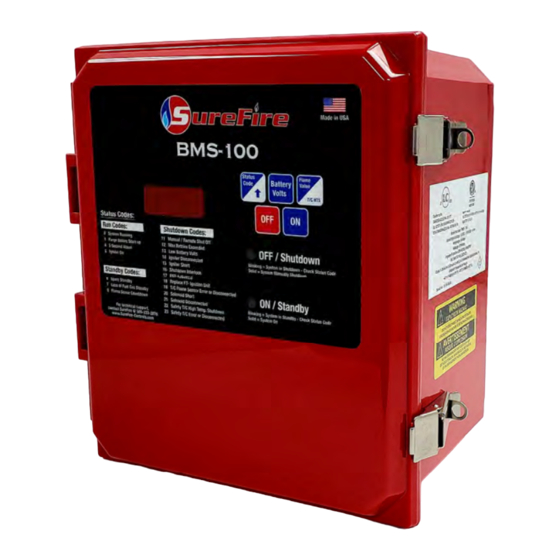
Page 7: Bms-100 Description
BMS-100 Description Enclosure: The SureFire BMS-100 system uses a polycarbonate NEMA 4X Enclosure to house the circuit board. The Graphic overlay, with membrane keypad is mounted on the exterior of the enclosure. The NEMA 4X enclosure provides a high level of protection from harsh outdoor elements: Windblown Dust Protection ... - Page 8 BMS-100 Description BMS-100 Circuit Board: The SureFire BMS-100 System is controlled by state of the art, non-arcing, electronics that monitor and control all burner functions. It comes with 2 LED indicators and a LED display. It also comes with individual...
- Page 9 BMS-100 Description LED Indicators: The circuit boards LEDs illuminate through the lid of the enclosure. The LED’s indicate the following: LED Indicator Status LED ON - Indicates that the system is on and operating properly GREEN Blinking - Indicates a standby switch has been activated...
- Page 10 BMS-100 Description 5 Button Keypad: The SureFire BMS-100 System has a 5 button Key Pad to control and monitor the system. The buttons perform the following functions: Button Displayed Value / Functional Operation Press once (while in locked mode) - Turns the system On ...
-
Page 11: Surefire Ignition Units
Armored wiring harness rated to 1000°F duty and 1500°F flash Direct termination to the BMS-100 Controller For proper pilot placement and flame sensing selection, contact SureFire Tech Support @ 505-333-2876 or the local SureFire representative... - Page 12 of a flame Armored wiring harness rated to 1000°F duty and 1500°F flash Direct termination to the BMS-100 Controller For proper pilotless ignition unit and orifice sizing, contact tech support @ 505-333-2876 or the local SureFire representative...
-
Page 13: Surefire Additional Components
Proof of valve closure switch kit available Applications include– non-venting pilotless fuel trains, double block fuel trains, fuel trains for combustors and flare systems. 1” & 2” SureFire Solenoid Valve: Fail-closed device. No adjustment necessary. Simple termination and installation. - Page 14 SureFire Additional Components 1/4” ASCO Solenoid Valve: Fail closed device. No adjustment necessary. Simple termination and installation. Applications include– direct pilot (#72 orifice) and pneumatic valve operation. 1/2” Pressure Switch: Used on a variety of standbys and shutdowns ...
-
Page 15: Installation Guide
Before any welding is attempted, disconnect all wires going to the circuit board. Any damage caused by welding to the SureFire BMS is NOT covered under warranty. Before terminating any wires, be sure no power is supplied to the controller. - Page 16 2nd Stage Valve Control: SureFire Actuator Valve: 1. Install a SureFire Actuator Valve in the fuel train on the main vent line to the combustor. 2. Terminate wires on terminal block labeled Actuator Valve (1, 2 & 3) from the Actuator Valve terminal ports (1, 2 &...
- Page 17 Installation Guide Loss of Fuel Gas and Spare Standby: 1. If ports are not used, a jumper is required on ports 17 & 18 and 19 & 20. 2. When using a device, install a normally open or close dry contact device, terminate wires from device in one of the assigned terminals.
- Page 18 2. Connect negative (-) terminal to port 31. 3. Connect positive (+) terminal to port 32. NOTES: If battery is more than 10 feet away from SureFire controller, use larger wire as needed. If utilizing 12 VDC power supply, set voltage @ 13.4 VDC.
-
Page 19: Specifications
Specifications Power Supply Specifications Battery Volts 12 - 13.4 VDC 12 VDC Power Supply Set @ 13.4 VDC Solar Panel 12 VDC / 75 W Max System Amperage 5.0 Amp / 0.6 Amp Avg. Ignition Unit Specifications Ignition Unit @ Inrush 6.5 Amps Ignition Unit @ Steady State 2.0 Amps Nominal (during ignition only) -
Page 20: Run Status, Alarm Out And Flame Strength
Run Status, Alarm Out and Flame Strength Run Status and Alarm Out Operational States: Unit Status Run Status Alarm Out Green LED Red LED Manual OFF Open Open Shutdown Open Open Blinking Standby Open Closed Blinking Unit ON Closed Closed (Status Code 00) Flame Strength Value Information: Thermocouple... - Page 21 Wiring Diagram...
- Page 22 1” Solenoid Fuel Train Diagram...
- Page 23 1” Solenoid & Actuator Valve Fuel Train Diagram...
- Page 24 Asco, 3PG & Actuator Fuel Train Diagram...
-
Page 25: Bms-100 Setup / Menu
BMS-100 Setup / Menu Menu Access 1. Press and hold the OFF button to unlock the system. 2. The display will show 0000 to indicate the system is unlocked. 3. The display will flash OFF. 4. The Battery Volts button is pressed to open or enter the menu. - Page 26 BMS-100 Setup / Menu Pre-Purge Timing - S-03 The third mode in the menu is the pre-purge timing. This selection is the timing allotted prior to ignition (both initial startup and between ignition attempts) allowing raw combustible gas for safety purposes.
- Page 27 BMS-100 Setup / Menu Pressure High End Setpoint - S-06 The sixth mode in this menu is the pressure low end setpoint. This setpoint is the ounce / pressure setpoint that will determine at what input pressure the actuator valve or main valve will open.
- Page 28 1 = Actuator opens 30 seconds after the stage 1 solenoid valve Adder Card Operation - S-09 The ninth mode within the menu determines whether the BMS-100 is functioning with or without an adder card. 0 = No adder card included in the setup / operation...
- Page 29 BMS-100 Setup / Menu Data Logging - S-11 thru S-15 The eleventh thru fifteenth modes allow the date and time to be setup for the data logging function. S-11 sets the minute: i.e. 15 xx:15 S-12 sets the hour: i.e. 4...
-
Page 30: Sequence Of Operation
Sequence of Operation Ignition Process: 1. Press the ON Button 2. Pre-purge - 180 second countdown displayed. Green LED ON. 3. Audible Alarm - 5 second countdown displayed. Green LED ON. 4. Igniter ON - 8 second countdown displayed. Green LED ON. - Page 31 Sequence of Operation without Adder Card Flow Chart:...
- Page 32 Sequence of Operation with Adder Card Ignition Process: 1. Press the ON Button 2. Pre-purge - Pre-purge countdown displayed. Green LED ON. 3. Audible Alarm - 5 second countdown displayed. Green LED ON. 4. Igniter - 8 second countdown displayed. Green LED ON.
- Page 33 Sequence of Operation with Daughter Board-Features Flow Chart:...
-
Page 34: Troubleshooting Guide
Troubleshooting Guide Run Codes: Code Symptom Action Normal Operation Pilot flame is present Green LED ON Display reads On or Flame sensing System No errors thermocouple temperature value Running Normal Operation Pilot flame not present Green LED ON ... - Page 35 Troubleshooting Guide Shutdown Codes: Code Symptom Action System turned off Manually or remotely Red LED ON (Ports 15&16 received a remote signal) Pilot flame not present Display shows OFF Manual/Remote To restart system press the ON button ...
- Page 36 Troubleshooting Guide Shutdown Codes: Code Symptom Action System detecting an open circuit Jumper is not installed Pilot flame not present Ports require a jumper when not used Blinking Red LED No activity when attempting start-up Shutdown ...
- Page 37 Troubleshooting Guide Shutdown Codes: Code Symptom Action Solenoid wires are making contact with one Pilot flame not present another. Blinking Red LED No activity when attempting start-up Solenoid wires are making contact with Solenoid Short ground ...
- Page 38 Combination Card Information Combination Adder Card The SureFire Combination Adder Card includes Modbus Communications, High Temperature Safety Thermocouple, 4-20mA Input and Data Logging. Modbus communication through RS-485 communication protocol. Please refer to the Modbus section of this manual for more complete details.
-
Page 39: Modbus Information
100, the BMS-100 firmware needs to be version 3.6 or greater. Introduction: The Modbus interface to the BMS-100 is accomplished via an intermediary processor board, the BMS Combination Card. The function of this board is to serve as a Modbus RTU slave, handling requests from the Modbus master to read information and relay command data to the BMS-100 board. - Page 40 Modbus Information Basic Read Operation: Basic operation of the BMS-100 with Modbus is as follows: For reading a register (or registers) the Modbus master sends a holding register read request to the BMS Modbus board using Modbus Function 03 (see “MODBUS APPLICATION PROTOCOL...
- Page 41 Modbus Information Modbus Register Name Data Type Notes Address Modbus Master 40,007 Max Retry Value Unsigned Int. 16 Bit 9...0 is 1 - 9,999 Attempts Pre-Purge Timing 40,008 Unsigned Int. 16 Bit 9...0 is 1 - 9 Minutes Setpoint Safety Thermocouple Bit 9...0 is 100°F - 2,400°F 40,009 Unsigned Int.
- Page 42 Modbus Troubleshooting Symptom: The LED on the Combination Card is not flashing. Discussion: The LED only flash when intact (complete and correct) packets are received from their respective interfaces. If the data arrives garbled, or if no data is sent, then the corresponding LED will not flash.
- Page 43 BMS-100 Installation and Operations Manual: Last Update: November 29th, 2022 Version: 3.5 SureFire Farmington, NM Office: Mailing Address: 1910 Rustic Place, Farmington, NM 87401 Phone: (505) 333 - 2878 SureFire Houston, TX Office: Mailing Address: 12510 Cutton Road, Houston, TX 77066...
Need help?
Do you have a question about the BMS-100 and is the answer not in the manual?
Questions and answers