Table of Contents
Advertisement
Quick Links
Advertisement
Table of Contents

Related Manuals for Surefire BMS-350


Summary of Contents for Surefire BMS-350
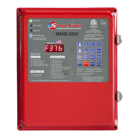
- Page 1 INSTALLATION & OPERATIONS MANUAL PROUDLY MADE IN THE USA...
-
Page 2: Table Of Contents
Table of Contents Table of Contents System Introduction Certification and Warnings Warranty and Return Policy System Description 6 - 9 Product Information 10 - 13 Installation Guide 14 - 18 Specifications Run Status and Flame Strength Information ... -
Page 3: System Introduction
BMS-300 System Introduction The BMS-350 is designed for heavy duty oilfield applications and is certified to UL and ISA standards for hazardous areas. The BMS-350 is designed to operate with the FT Ignition units to provide optimal ignition. The controller’s display is designed to operate in ambient temperature from –40°F to 131°F, and is coated for corrosion resistance. -
Page 4: Certification And Warnings
Certifications and Warnings ETL Certified to the Following 7.8 amps @ 12.0 vdc MAX Standards: 0.025 amps @ 12.0 vdc AVG CERTIFIED TO: CONFORMS TO: CSA STD C22.2 NO. 61010-1 UL STD 61010-1 CSA STD C22.2 NO. 213:2017 Ed.3 UL STD 121201:2017 Ed.9 *WARNING* EXPLOSION HAZARD –... -
Page 5: Warranty And Return Policy
The warranty policy is related to manufacturing defects. The return policy is related to the return of product for any reason other than manufacturing defects. Returns must be approved by SureFire in advance of shipment and returned products must be in their original condition. Restocking fees for returns are at the discretion of SureFire and may vary by product. -
Page 6: System Description
BMS-350 Description Enclosure: The SureFire BMS-350 System uses a polycarbonate NEMA 4X enclosure to house the circuit board. The graphic overlay with membrane keypad is mounted on the exterior of the enclosure. The NEMA 4X enclosure provides a high level of protection from harsh outdoor elements: Windblown Dust Protection ... - Page 7 BMS-350 Description BMS-350 Circuit Board: The SureFire BMS-350 System is controlled by state of the art, non-arcing electronics, that monitor and control all burner functions. It comes with 4 LED indicators and a LED Display. It also comes with individual terminal blocks, ground lug, and power connector to ease wiring and installation.
- Page 8 BMS-350 Description LED Indicators: The circuit boards LEDs illuminate through the lid of the enclosure. The LED’s indicate the following: LED Indicator Status LED ON - Indicates that the system is on and operating properly GREEN Blinking - Indicates a standby switch has been activated...
- Page 9 BMS-350 Description 16 Button Keypad: The SureFire BMS-350 System has a 16 button keypad to control and monitor the system. The buttons perform the following functions: Button Displayed Value / Functional Operation Increases the current value Up Arrow ...
-
Page 10: Product Information
Kanthal flame rod rated 2600°F Armored wiring harness to 500°F duty / 800°F flash Direct termination to BMS-350 controller For proper pilot placement and flame sensing selection, contact SureFire Tech Support @ 505-333-2876 or the local SureFire representative... - Page 11 Utilizes temperature reading to verify the presence of a flame Armored wiring harness rated to 1000°F duty and 1500°F flash Direct termination to the BMS-350 Controller Flame Rod: Kanthal flame rod rated 2600°F Armored wiring harness to 500°F duty / 800°F flash ...
- Page 12 Proof of valve closure switch kit available Applications include– non-venting pilotless fuel trains, double block fuel trains, fuel trains for combustors and flare systems. 1” & 2” SureFire Solenoid Valve: Fail-closed device. No adjustment necessary. Simple termination and installation.
- Page 13 SureFire Additional Components 1/4” ASCO Solenoid Valve: Fail closed device. No adjustment necessary. Simple termination and installation. Applications include– direct pilot (#72 orifice) and pneumatic valve operation. 1/2” Pressure Switch: Used on a variety of standbys and shutdowns ...
-
Page 14: Installation Guide
Before any welding is attempted, disconnect all wires going to the circuit board. Any damage caused by welding to the SureFire BMS is NOT covered under warranty. Before terminating any wires ensure no power is supplied to the controller. - Page 15 1. Ensure main supply gas is shut off. 2. Locate the pilot gas supply line and eliminate the pilot fuel train completely. 3. Install the SureFire Actuator Valve in the fuel train on the main burner line down steam of the main burner control valve.
- Page 16 Terminal block 2 @ SureFire Actuator port 2 Terminal block 3 @ SureFire Actuator port 3 Must use a SureFire Actuator valve or an actuator approved by SureFire. ASCO Solenoid proper flow direction: 2 = Inlet and 1 = ...
- Page 17 Installation Guide Standby Ports: When using a device, install a normally open or closed dry contact device into ports and 20 & 21 and 22 & 23. If no device is used, a jumper is required on afore mentioned ports.
- Page 18 3. Connect positive terminal to port # 35 NOTES: If the battery is more than 10’ away from the SureFire controller, use larger AWG wire as needed. If utilizing a 12 VDC power supply, set volt- age @ 13.4 VDC. The power supply should...
-
Page 19: Specifications
Specifications Power Supply Specifications Battery 12 VDC - 14.5 VDC 12 VDC Power Supply Set @ 13.4 VDC Solar Panel 12.0 VDC Only - 75 Watt Max 24 VDC 24.0 VDC Ignition Unit Specifications 7.5 Amps Inrush, 2.0 Amps NOM (During Igniter Current Draw Normal Operation) Sensor Specifications... -
Page 20: Run Status And Flame Strength Information
Run Status and Flame Strength Information Run Status Operational States: Operational State Alarm Out Green Blue Amber System OFF or Manual Open Open Shutdown System ON, Pre-purge Close Open complete, igniter on Flame sensed, Burner Close Close running, No Errors Shutdown, Igniter Error Open Open... - Page 21 Wiring Diagram...
-
Page 22: Diagrams
Fuel Train Diagrams Pilotless Fuel Train: Piloted Fuel Train:... -
Page 23: System Setup
Low Temp range: RTD = 32°F - 588°F / Thermocouple = 32°F - 2,398°F NOTE: The SureFire System comes with a standard 2°F temperature span between the High Temp and the Low Temp to prevent undue wear and tear associated with equipment short cycling. - Page 24 BMS-350 Setup Flame Sense - Flame Rod (F) or Thermocouple (H): Flame Sense 1. The button displays the current flame sensing device. 2. To adjust the flame sensing device: Up Arrow Unlock the system by pressing and holding the button for 5 seconds until a series of ...
- Page 25 BMS-350 Setup Extreme High Temperature Delta (EHTD): EHTD button displays the current Extreme High Temperature Delta setpoint. To adjust the Extreme High Temperature Delta: EHTD Press the button to view the current setpoint. Up Arrow Unlock the system by pressing and holding the button down for 5 seconds until a ...
- Page 26 BMS-350 Setup Pilot Mode - Intermittent (1) or Standing (2): Pilot Mode button displays the current pilot mode. To adjust this Pilot Mode: Pilot Mode Press the button to view the current setting. Up Arrow Unlock the system by pressing the button for 5 seconds until a series of zeros appear.
- Page 27 BMS-350 Setup Solenoid Timing: Solenoid Timing 1. The button displays the current amount of time that elapses between the first stage Solenoid valve opening and the second stage Solenoid valve opening. 2. To adjust the Solenoid Timing setpoint: Solenoid Timing Press the button to view the current timing setpoint.
- Page 28 2. To view the current supply voltage, press the button. NOTE: The SureFire BMS-350 system accepts voltages defined in the specification section of this manual on page No. 19. This system is able to measure the battery / power supply voltage at all times; however, it does not re- ...
-
Page 29: Sequence Of Operation
Intermittent Pilot Sequence of Operation Ignition Process: 1. Press the ON button. 2. Pre-purge - 120 second countdown displayed - LED ON. 5. Audible Alarm - 5 second countdown- Green LED ON. 6. Igniter on - 5 second countdown - Green Amber LED ON. - Page 30 Intermittent Pilot Sequence of Operation Flow Chart:...
- Page 31 Standing Pilot Sequence of Operation Ignition Process: 1. Press the ON button 2. Pre-Purge - 120 second countdown displayed– LED ON 5. Audible Alarm - 5 second countdown - Green LED ON 6. Igniter on - 5 second countdown- Green Amber LED ON 7.
- Page 32 Standing Pilot Sequence of Operation Flow Chart:...
- Page 33 Pilotless Sequence of Operation Ignition Process: 1. Press the ON button 2. Pre-Purge - 120 second countdown displayed– LED ON 3. Audible Alarm - 5 second countdown - Green LED ON 4. Igniter on - 5 second countdown- Green and Amber LED ON 5.
- Page 34 Pilotless Sequence of Operation Flow Chart:...
-
Page 35: Troubleshooting Information
Troubleshooting Guide Run Codes: Code Symptom Action Normal operation. Blue and Green Pilot/main burner is on. Successful ignition recorded System LEDs ON Process temperature increasing. Running Normal operation. Process temperature reached high Pilot/main burner is not on. temp setting. - Page 36 Troubleshooting Guide Shutdown Codes: Code Symptom Action System was manually or remotely Pilot/main burner is not Manual / turned OFF. Red LED ON Remote Shut To startup system press the ON button. Check fuel supply. Check power supply. ...
- Page 37 Troubleshooting Guide Shutdown Codes: Code Symptom Action Ensure proper flame sensing mode is selected. Pilot/main burner is not Flame rod wire shorting against Blinking Red Flame Sensed ground. No activity when system Before Startup Flame Rod shorting against ground. ...
- Page 38 Troubleshooting Guide Shutdown Codes: Code Symptom Action Pilot/main burner is not Inspect device for faulty operation. Verify wiring from device. Blinking Red Stage 1 No activity when System detecting battery volts 11 Solenoid Valve attempting startup VDC - verify battery voltage.
-
Page 39: Modbus Information
The Modbus registers, their contents, command sequencing and examples of command execution over Modbus are described. This document applies to firmware revisions 2.0. In order to use Modbus 2.0, the BMS-350 firmware package needs to be 2.74. 1.0 Introduction: The Modbus interface to the BMS-350 is accomplished via an intermediary processor board, the BMS Modbus board. - Page 40 Address 40002 maps to Register 2 ↓ ↓ ↓ Address 40255 maps to Register 255 The following table is the register map for the BMS-350. Bits are in Most Significant Bit (MSB) first order. Register name Modbus Modbus master does Data type Notes...
- Page 41 Modbus Information Register name Modbus Modbus master does Data type Notes address R (Read) or RW (Read or Write) Bit 0 – System LED status 0 : RED LED solid - System OFF 1 : GREEN LED solid - System running Bit 1 –...
- Page 42 Modbus Information Register name Modbus Modbus master does Data type Notes address R (Read) or RW (Read or Write) 0x55 IDLE - Ready for new command 0x01 Command executed OK 0x02 Bad command, nothing done 0x03 BMS read of exec reg from Modbus board timed out 0x04 BMS read of exec packet from Modbus board had bad checksum 0x05 BMS read of cmd reg from Modbus board timed out...
- Page 43 Modbus Information Register name Modbus Modbus master does Data type Notes address R (Read) or RW (Read or Write) 40016 thru Unallocated unsigned int 16 Read as zero, can be written to but will be ignored. 40019 Bit 0 – System LED sta- Bit #0 of register 40005 unpacked into a single 0:RED LED solid - Sys- 40020...
- Page 44 Modbus Information Register name Modbus Modbus master does Data type Notes address R (Read) or RW (Read or Write) Bit 9 – RED LED Bit #9 of register 40005 unpacked into a single unsigned int 40029 0 : Not blinking register for use by controllers with primitive bit 1 : Blinking manipulation capabilities.
- Page 45 Modbus Information 4.0 Command Operation: Command operation on the BMS-350 utilizes the “mailbox” concept. The general sequence is as follows: 1. MASTER reads Command Status register (Modbus 40010). If it reads as 0x55 (IDLE) then proceed. Otherwise wait a short time (a few hundred ms would be reasonable) and poll that register again.
- Page 46 Modbus Information The following table shows the switch settings for SW1-1 through SW1-5 required to obtain the desired Modbus address: Desired Modbus SW1-1 SW1-2 SW1-3 SW1-4 SW1-5 address...
- Page 47 DISCUSSION: Due to the hardware constraints on the BMS-350, the LED display will flicker slightly during normal operation when the Modbus is in use. If the Modbus master polls the BMS-350 for data at a rapid rate, or transfers many registers during each poll, the flickering becomes worse. If the Modbus is being queried on a continuous basis, the display and keypad may become difficult to operate.
-
Page 48: Software Versions
Software Versions BMS-350 Software Version Release Date Description V2.5 05/08/2019 Standard base software MODBUS Software Version Release Date Description V2.0 05/06/2019 Standard base software Serial Number: Software Version:... -
Page 49: Notes
Installation Notes... - Page 50 Installation Notes...
- Page 51 Installation Notes...
- Page 52 BMS-350 Installation and Operations Manual: Last Update: 02/02/2021 Version: 6.0 SureFire Farmington, NM Office: Mailing Address: 1910 Rustic Place, Farmington, NM 87401 Phone: (505) 333 - 2878 Fax: (505) 333 - 2879 SureFire Houston, TX Office: Mailing Address: 12510 Cutten Road, Houston, TX 77066...
Need help?
Do you have a question about the BMS-350 and is the answer not in the manual?
Questions and answers