Table of Contents
Advertisement
Quick Links
Advertisement
Chapters
Table of Contents

Related Manuals for FlexQube eQart


Summary of Contents for FlexQube eQart
- Page 1 User manual. Date 01 / 2023 Revision...
-
Page 2: Copyright And Disclaimer
FlexQube makes no warranties in respect of this document or its contents. The content of this document is subject to change without prior notice. Every precaution has been taken in the preparation of the user manual. -
Page 3: Table Of Contents
Copyright and disclaimer ..........................1 Introduction to this document ........................ 4 Document history ........................... 4 eQart Introduction ..........................5 Additional information about the eQart ..................5 Safety ..............................6 Safety message types ........................6 Important safety notifications ......................6 eQart Certification .......................... 7 Intended use ........................... - Page 4 User applications........................... 26 Stand alone ........................... 26 Towing ............................26 Mother/daughter ......................... 26 Unpacking of the eQart ......................... 27 Accessories with the eQart ......................27 Starting up the eQart ........................28 Unboxing of the eQart ........................29 Cockpit Operation ..........................31 10.1...
-
Page 5: Introduction To This Document
1 Introduction to this document This information will give you the following knowledge. • Unboxing of the eQart. • Startup, implementation, and operation of the eQart. • Technical description of the eQart. • Maintenance of the eQart. 1.1 Document history... -
Page 6: Eqart Introduction
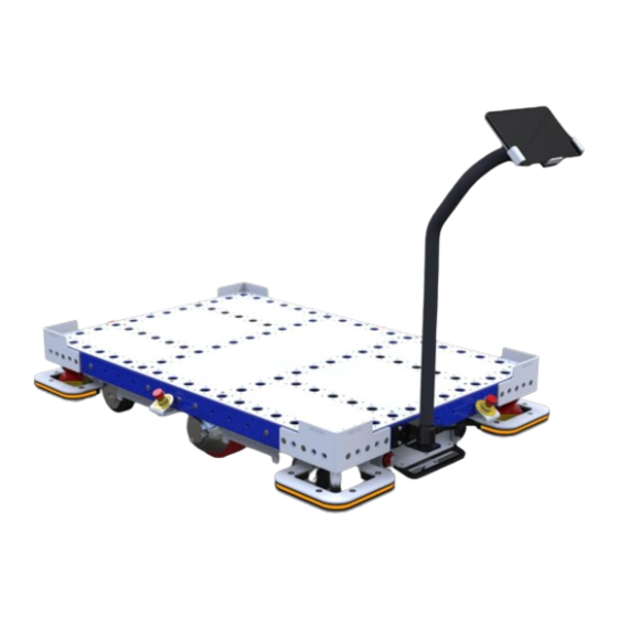
The eQart is ideal for recurring transports such as A to B or circular flow layouts. The eQart has a modular architecture enabling sizes from 910 x 840 mm up to 2520 x 2520 mm. The modules creating the eQart is the: 1. -
Page 7: Safety
The laser scanner has a planar reading area 150 mm above the floor. Any object below OR above this level will not be visible for the eQart. Make sure that the route is clear from obstacles that are not visible to the eQart safety systems. Otherwise, it can result in major damage and cause eQart to collide with objects and make the load fall off. -
Page 8: Eqart Certification
The eQart is certified according to the Machinery Directive 2006/42/EC, which includes the base platform for L x W (Length x Width) between 840 mm to 2520 mm (Minimum eQart size should be 910 mm x 840 mm). The eQart is certified and adheres to the following standards: •... -
Page 9: Risk Assessment Of The Complete Application
3.6 Risk assessment of the complete application The operator of the eQart is responsible for making a risk analysis of the complete use scenario and process in each implementation related to the user’s facility. Examples of risks to consider are route planning, crossing traffic, safe loading and unloading of the eQart, etc. -
Page 10: Fail-Safe Motors
3.8.3 Fail-safe motors In case of power loss, the eQart brakes are applied and the eQart motors are braked to avoid unintended motion of the eQart. The brakes can only be released by the activation of power. -
Page 11: Product Specification
▪ 910 mm x 840 mm (Smallest), ▪ 2520 mm x 2520 mm (Largest) ▪ The eQart can be configured to any size between the smallest and largest size in increments of 70 mm Length 1050 1120 1190... - Page 12 The floor should be dry and clean for the tape installation. ▪ The installation place should be free from moisture. The eQart serial number and CE Marking is stamped on a sign attached to the eQart base. Automation your way...
-
Page 13: Nameplate & Markings
The UKCA, FCC Standard and CE certification marking is displayed on the nameplate according to requirements. • The nameplate specifies the data of the eQart mass, the requirement of power, year of manufacture, max. load to be allowed and battery specification. Figure 1 Example of the eQart Nameplate... -
Page 14: Mechanical Design
User manual rev. 1.7 5 Mechanical design The eQart is based on eight smart modules enabling a high degree of scalability and flexibility in design. 1. Brain Module (onboard computer & visual system) 2. Battery Module 3. Motor Module 4. -
Page 15: Brain Module
The Brain Module contains the computing unit and cameras that handles the Line follow functionality. • The Brain module is placed in the center in between the motor modules of the eQart. • The Brain module and its onboard computer control all the systems/functionality of the eQart. -
Page 16: Battery Module
The Swap Battery Module is a removable battery that allows for simple swapping to handle all day operation with very low downtime. • eQart is equipped with a 60 Ah Li-ion battery. • Special care must be taken when removing the battery module from the cart. -
Page 17: Fixed Battery Module
User manual rev. 1.7 5.2.2 Fixed Battery Module The Fixed Battery Module is a stationary battery package. • The fixed battery module is only available with HW 1.0 & HW 2.0. • The Fixed Battery module contains a 60 Ah Li-ion battery. -
Page 18: Emergency Stop Module
5.4 Emergency Stop Module The Emergency Stop Module has a physical button to trigger the safety system to trigger the brake of the eQart when in operation or to make sure the eQart is safe during maintenance. • The emergency stop module is mounted on all four sides of the cart for easy access. -
Page 19: Led Corner Module With Laser Scanner
User manual rev. 1.7 5.6 LED Corner Module with Laser Scanner The LED Corners is used to signal the status of the eQart to people in its vicinity. The Laser scanner is used to detect objects around the eQart. -
Page 20: Tablet Holder Module
User manual rev. 1.7 5.8 Tablet Holder Module The Tablet Holder module is placed on the front side of the eQart or the side depending on the eQart application. • The stand for the tablet can be used to store and charge the tablet via the USB-C charging cable integrated into the stand. -
Page 21: Laser Scanner Functionality
The eQart is equipped with an ISO 13849:1 safety rated laser scanner used to detect objects in the eQart’ s traveling path, bringing the cart to a safe stop before colliding with a person or an obstacle. 6.1 Laser scanners The Laser scanners are supplied by Hokuyo and certified according to ISO 13849-1 cat D. -
Page 22: Figure 11 Sensor Operations
This zone is ISO 13849-1 certified. • If the eQart stops and laser’s optical window shows 85 error, then the user must clean the sensor’s optical window with a cotton cloth. •... -
Page 23: Lidar Error Code Troubleshooting
User manual rev. 1.7 6.3 Lidar Error Code Troubleshooting There section describes troubleshooting methods while lidar shows error code. Error Details Possible reason Solution suggestion Number Area input connection Confirm the input status Check the encoder error during area switching. -
Page 24: Led Light Functionality
User manual rev. 1.7 7 LED Light Functionality The eQart has LED corner modules located in each corner of the eQart with RGB light that lights up or blinks according to the mode of operation. 7.1 For Manual Drive... -
Page 25: Line Follow Drive
User manual rev. 1.7 7.2 Line Follow Drive When the eQart operates in Line Follow Drive it will only blink in the driving direction, when switching direction in the eQart Cockpit it will switch to the LEDs in the opposite direction. -
Page 26: Figure 15 Led Indicators For Additional Operations
A. The LED blink GOLD on all 4 LEDs, when junction start to finish in map recording. B. The LEDs blink Midnight BLUE, when eQart is in sleep mode. C. The LEDs blink CYAN, when eQart is ready to operate. -
Page 27: User Applications
8.2 Towing The eQart can be used to tow tugger carts using either a tow bar or a hitch placed on the rear side of the eQart. An eQart used for towing needs 1000 kg (2200 lbs) of payload to ensure traction for good towing capability. -
Page 28: Unpacking Of The Eqart
User manual rev. 1.7 9 Unpacking of the eQart The eQart comes delivered in a wooden box including the eQart itself and all the accessories needed for set-up. Follow the procedure to safely unpack the eQart. 9.1 Accessories with the eQart... -
Page 29: Starting Up The Eqart
User manual rev. 1.7 9.2 Starting up the eQart 1. The eQart ON/ OFF switch is placed in front of the battery module. To start the eQart make sure to deactivate all emergency stop buttons. 2. Rotate the ON/OFF Switch clockwise to turn on the eQart as shown below. -
Page 30: Unboxing Of The Eqart
1. Remove the screws in the lid which is attaching the front side and the top lid to the box. 2. Remove the front lid from the box. 3. Take off the top lid and place it on the floor as shown in the image. The eQart now has a ramp to roll out of the box. -
Page 31: Figure 20 The Eqart Unboxing 2
7. When attaching the maintenance drive to the eQart a “click” should be present. This means brakes of the eQart is released. 8. Now the eQart can roll out of the box by manually pulling the eQart out of the box, Figure 20 The eQart Unboxing 2... -
Page 32: Cockpit Operation
• Connect the eQart with a tablet, then open eQart application. 1. The eQart Cockpit app is also pin protected, the pin code will be provided with the eQart delivery. Figure 21 eQart Cockpit App lock •... -
Page 33: Figure 22 Eqart Cockpit Main Menu
2. Users can also change the language of the application. (English or German) • When the eQart is not connected with wifi, the pop-up message shows that “You are not connected with eQart”. Figure 23 eQart Cockpit “Not connected” message... -
Page 34: Cockpit
User manual rev. 1.7 • In case, when the eQart is connected with one tablet and another user tries to connect to that eQart by another tablet, then the pop-up message will appear that “eQart is connected with another tablet”. -
Page 35: Manual Drive
The eQart can drive manually controlled by the user in the eQart Cockpit. 1. The eQart can run with top speed of 0.7 m/s in line follow as well as manual mode with HW 2.0. 2. The eQart can run with top speed of 1 m/s in line follow as well as manual mode with HW 3.0. -
Page 36: Line Follow
• By placing the eQart with its center on the line, the eQart will detect the line and the blue line will light up and a pop-up reading "Connected to the line" will appear in the eQart Cockpit, the eQart is then able to start line follow. -
Page 37: Figure 27 Eqart Cockpit In Line Following Operation
• When driving on a straight main color line the full speed of the eQart is up to 0.7 m/s with HW 2.0 & 1 m/s with HW 3.0. At curves, the eQart will naturally slow down to handle navigation. -
Page 38: Map & Routes
User manual rev. 1.7 10.2 Map & Routes The eQart can record a map with all the routes to each of the stations mapped on the floor automatically. By using this map, the user can easily send the eQart to predefined stations around the factory. -
Page 39: Figure 29 Step 2 In The Mapping Guide
User manual rev. 1.7 2. Place tags • The RFID tag is placed at all the positions where the eQart will make a stop as well as on all the endpoints in the layout. • The RFID tag placed under approx. 600 mm of station color tape. The default setting station color tape is red and the main color is blue. -
Page 40: Figure 31 Step 4 In The Mapping Guide
Simple map: Always start the recording facing one of the end stations. Figure 31 Step 4 in the mapping guide 5. Place the eQart • Drive the eQart and place in line in front of the RFID tag. Figure 32 Step 5 in the mapping guide Automation your way... -
Page 41: Figure 33 Step 5 In The Mapping Guide
User manual rev. 1.7 6. Direction • Make sure that the eQart LEDs are flashing Orange towards the RFID tag. Figure 33 Step 5 in the mapping guide Automation your way... -
Page 42: Create A New Route
RFID tag name and then continues towards the next station. • eQart always turns LEFT when it moves around the layout during mapping to find all paths, corners, and intersections. •... -
Page 43: Figure 35 Map & Routes Screen In The Eqart Cockpit
Pick what type of map to record: 1. Simple Path: A simple path means that there is no closed loop in the path. Start recording a map from the end station placing the eQart center right before the RFID tag. -
Page 44: Figure 37 Map Routing Of Eqart
Following is an example of how the eQart creates the map: 1. The eQart is located at Stop - 04 and starts to create a map as shown in “Figure 37 Map Routing of eQart”. -
Page 45: Recorded Maps
“Download maps” feature. • Users can share these maps with different users. • The recorded map is stored in the eQart Cockpit. It can also be uploaded to cloud storage using share functionality between different eQart. Figure 38 Recorded maps view •... -
Page 46: Figure 40 How To Change The Rfid Tag
• If the cart is at Stop – 126 and user select destination as Stop – 125, the eQart finds the shortest route. After pressing the start button the eQart starts to travel towards Stop –... -
Page 47: Mission Planner
User manual rev. 1.7 10.3 Mission Planner The eQart Mission Planner is used to program a series of task that will be performed by the eQart automatically without or with reduced operator interaction. This allows the users to program a custom mission that is adopted to a specific process. The eQart can navigate between a series of stations without any operator input as well as wait at a station for a fixed amount of time, wait for operator confirmation and looping the mission. -
Page 48: Figure 44 Mission Planner Programming View
User manual rev. 1.7 4. In the "Mission Planner" page the user is able to program a series of task by dragging and dropping the function blocks on the right-hand side into the mission sequence. Figure 44 Mission planner programming view. -
Page 49: Figure 46 Mission Planner, Adding "Go To Station
• Wait (x) seconds The "Wait (x) seconds" block is used to tell the eQart to stay at a station, this can be used if the process requires a fixed amount of time for loading or unloading. After dropping the block into the flowchart, press the block to specify the time to wait in seconds. -
Page 50: Figure 48 Mission Planner, Adding "Rotate On Point
• Rotate on Point With "Rotate on point" the eQart will be turning around its own axis on point. Dragging the block into the flowchart and pressing the block to decide what type of rotation the eQart will perform. The change direction allows the eQart to either return backwards or if activated continue straight after the rotation. -
Page 51: Figure 50 Mission Planner, Adding "Battery Percentage
The "Press tablet" block can be used to trigger a pop-up message on the tablet screen, this can be used to allow an operator to confirm when he has completed the task at that station. After confirming the trigger message, the eQart will continue with the mission. •... -
Page 52: Figure 51 Mission Planner, Adding "If Condition
User manual rev. 1.7 Conditional blocks: • If Condition With the "If Condition" the user can create a decision condition to allow the operator to pick between two different actions. When pressing the If Condition, a rhomb is created in the flowchart, then pick two different blocks and place on either side like below to create a decision tree. -
Page 53: Figure 53 Mission Planner, Adding "Feedback
User manual rev. 1.7 • Feedback The "Feedback" block allows the user to create a loop in the mission to allow it to run continuously. This way the mission will be able to run all day until paused or interrupted. By pressing Feedback, the user will be prompted to first pick last block in the flowchart and then the second to specify to what block the loop should return to. -
Page 54: Figure 54 Mission Planner, Finalized Mission
User manual rev. 1.7 By using a combination of these blocks, the user will be able to create any time of mission that is required for the user’s process. When the mission is finalized, press "Save" and save the mission with appropriate name. -
Page 55: Run Mission
10.3.2 Run Mission ATTENTION The eQart must be located on top of the RFID tag on start station decided in the mission planner to be able to start the mission. There are two ways to start a mission in the eQart cockpit: 1. -
Page 56: Figure 58 Eqart Mission Planner View Of A Mission
3. In the Mission menu the user can press any of the saved missions which will bring up the mission view. If the eQart is located at the start station, the text will be marked in orange. By pressing "Start" the eQart will perform the mission as it was programmed. -
Page 57: Navigation
• Select the path direction from the edit map. • When the eQart has stopped on a station that has been recorded on the map, the eQart Cockpit shows the station as a source on the map. • Users can select the destination station on the map and from the list. -
Page 58: Settings
User manual rev. 1.7 10.5 Settings In the Settings menu, the user can access the settings for both the eQart and the Cockpit. There are three tabs in Settings: • General • Configuration • Diagnosis Figure 61 eQart Settings – General. -
Page 59: Settings > General
Settings > General Find eQart Purpose of "Find eQart" is to identify the connected eQart for specific Cockpit, when the user clicks on the "Find eQart" button, the buzzer sounds on the connected eQart and LED modules blinks with purple light. -
Page 60: Figure 64 Eqart Settings - Back Up And Download Data From Cloud
User can store their map and mission at cloud by clicking on this button. The log in must require for this. Figure 64 eQart settings – Back up and download data from cloud. Lock Mission Screen By checking the box, it enables the password protection for the running mission. By entering the correct password, user can exit the mission screen. -
Page 61: Settings > Configuration
Figure 67 eQart settings - Configuration. Select eQart size During eQart´s first set-up, it is necessary to select the eQart size. Since the eQart has a modular design some of its functions like map recording, 90 and 180-degrees rotation, line follow, etc. are dependent on the eQart size. -
Page 62: Figure 68 Eqart Settings - Select Eqart Size
Note This is only required for the initial start-up of the eQart. Figure 68 eQart settings – Select eQart size. Line color To ensure that the eQart line follow functionality is robust, the user can customize the line colors to Increase contrast between the line and the floor. •... -
Page 63: Figure 70 Eqart Settings - Ultrasonic Sensors
User manual rev. 1.7 Ultrasonic sensors The Ultrasonic sensors are an optional custom feature of the eQart. Users can opt for the extra Ultrasonic sensors option. The laser sensor can only detect objects in a single plane at a height of 160mm. For the users where the objects can be higher than this plane, the laser sensor cannot detect them. -
Page 64: Settings > Diagnosis
Figure 71 eQart settings – Add Flex Button. Lower detect window When the eQart faces light or color issue due to upper side of image, user can enable lower detect window. Now the eQart will use lower part of image for line following. -
Page 65: Figure 72 Eqart Settings - Diagnosis
Figure 73 eQart settings – Diagnosis. • Note The eQart will only create a Debug log for one line follow action after it is checked. If the eQart is put into line-follow mode a second time the Debug Log will be removed automatically. -
Page 66: Figure 74 Eqart Settings - Debug Log
To check the Debug log, click on the file icon to the right of the "Diagnosis" button as shown below: • The Debug log will present all the actions the eQart has recorded while in Diagnosis mode. Figure 74 eQart settings – Debug log. -
Page 67: Figure 76 Eqart Settings - Map Data Upload
If the eQart detects a faulty intersection while in line-follow mode it will lead to an error in the left/ right turning sequence. • If the eQart is in Map recording mode, the faulty intersection will lead to an error in the Map creation where it will not be usable in Navigation mode. •... -
Page 68: Figure 78 Eqart Settings -Intersection Images
All Images To make a general diagnosis for the line follow function or the Map recording the All images diagnosis can record all the images that eQart sees. • To start the All Images Diagnosis, check the All images box in the "Diagnosis" menu. -
Page 69: Maintenance Drive
User manual rev. 1.7 11 Maintenance Drive WARNING. Please read through safety instructions before using the Maintenance drive. When the eQart is stuck, and it is not possible to operate the eQart using the Cockpit, the user can use the Maintenance drive. •... -
Page 70: Maintenance
User manual rev. 1.7 12 Maintenance To ensure safe usage and long life for the eQart the following procedures must be followed regularly. 12.1 Lockout/ Tagout (LOTO) Safety Procedure The LOTO safety procedure is used when the eQart is in service or maintenance condition. -
Page 71: Maintenance Operation
User manual rev. 1.7 12.4 Maintenance operation ATTENTION. Check that the Emergency Stop button is applied while performing maintenance, as well as the main switch, should be OFF. The recommended Maintenance schedule is presented in the table below. The operator is responsible for doing regular cleaning, checkups, and smaller maintenance tasks. -
Page 72: Eqart Module Service
User manual rev. 1.7 12.4.1 eQart Module service To service the eQart modules, access under the eQart is needed to be able to replace the modules. To perform the service, it is needed to lift or flip over the eQart. • Brain Module ▪... -
Page 73: Figure 81 Bottom Of Eqart Showing The Eqart Modules
Disconnect the LED light cable and the Laser sensor cables connected to the Brain module. ▪ Remove the 4 self-tapping screws attaching the Corner module to the Base frame. ▪ The Corner module is now loose to be removed from the eQart. 4x Angled Battery 8x Bolts plates... -
Page 74: Maintenance Schedule
This will work only with HW1.0 & HW 2.0 not work for HW 3.0. • As a last step, the eQart can be lifted with a forklift by the included fork pockets under the eQart. Please note that many parts under the eQart are fragile so lift with caution. - Page 75 User manual rev. 1.7 List of Figures Figure 1 Example of the eQart Nameplate .................... 12 Figure 2 Exploded view of the mechanical design of the eQart............13 Figure 3 Brain Module ........................... 14 Figure 4 Swap Battery Module ......................15 Figure 5 Fixed Battery Module ......................
- Page 76 Figure 62 eQart Motor modules drive time................... 58 Figure 63 eQart Cloud login screen....................... 58 Figure 64 eQart settings – Back up and download data from cloud............. 59 Figure 65 eQart settings – lock mission screen..................59 Figure 66 eQart settings - About eQart screen.
- Page 77 User manual rev. 1.7 FlexQube HQ Aminogatan 20 431 53 Mölndal Sweden + 46 72 711 1477 FlexQube GmbH Feldbergstrasse 27-29 61440 Oberursel Germany +49 (160) 2436305 FlexQube Inc. 1875 East Main Street Duncan, SC 29334 +1 (843) 509 1624 www.flexqube.com...
Need help?
Do you have a question about the eQart and is the answer not in the manual?
Questions and answers