
Related Manuals for RVS SenseVue


Summary of Contents for RVS SenseVue
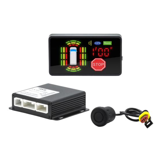
- Page 1 SenseVue Customizable Surround Sensor System w/ LED Display RVS-SenseVue (Up to 16 Sensors) Instruction Manual © Rear View Safety 2023...
-
Page 2: Table Of Contents
TABLE OF CONTENTS Table of contents ..................2 Introduction ....................3 Safety Information ...................4-5 Required Tools ....................6 System Content ....................6 Wire Diagram ....................7 Display Function ..................8 Sensor Location Requirements ..............9 Sensor Location Examples ..............10 Sensor and Sleeve Mounting ..............11 Door Installation Instructions ..............12 Harness Routing ..................13 ECU Installation ..................14 GPS and Display Locations ..............15... -
Page 3: Introduction
With this product, you are taking an active part in reducing dangerous road traffic events while keeping yourself, passengers, and pedestrians safe. This manual will take you step by step through the installation process and usage of SenseVue™. Please read all of the installation instructions carefully before installing the product. Improper installation will void manufacturer’s warranty. -
Page 4: Safety Information
Where the power cable may touch a metal case, cover the cable with • friction tape; a short circuit or disconnected wire may cause a fire While installing the RVS System, be careful with the wire positioning in • order to avoid wire damage Do not watch movies or operate the monitor while driving, as it may cause •... - Page 5 Any violation of traffic laws is the sole responsibility of the driver. RVS will not compensate the drivers for any damage caused to the driver and/or passengers of the vehicle and/or vehicle and shall have no responsibility arising from the behaviors mentioned above.
-
Page 6: Required Tools
REQUIRED TOOLS 25mm hole saw Electrical Tape Trim Removal tools Solder Wire cutters Painters tape and a marker Power Drill (driver bits and sockets needed) SYSTEM CONTENT Rear View Safety, 1797 Atlantic Ave., Brooklyn NY 11233 800.764.1028 sales@rearviewsafety.com www.rearviewsafety.com... -
Page 7: Wire Diagram
WIRE DIAGRAM 12 sensors - 3 on each side 14 sensors - 4 on each side 16 sensors - 6 on each side *other customization options available SENSOR PLACEMENT AND DETECTION RANGE 14 Sensors Placement 16 Sensors Placement Detection Range 8’... -
Page 8: Display Function
DISPLAY FUNCTION Rear View Safety, 1797 Atlantic Ave., Brooklyn NY 11233 800.764.1028 sales@rearviewsafety.com www.rearviewsafety.com... -
Page 9: Sensor Location Requirements
SENSOR LOCATION REQUIREMENTS Sensor installation height and the space between each sensor is important and will vary from vehicle type to vehicle type. Follow the basic requirements below and refer to the vehicle type suggestions that follow. For all sensor mounting locations, the mounting surface should be perpendicular to the ground, and should not point the sensor in a downward direction. -
Page 10: Sensor Location Examples
SENSOR LOCATION EXAMPLES Here are some basic vehicle types that the system can be installed on. Each blue “X” represents a sensor. Use these examples as a baseline when evaluating areas on a vehicle for side sensor placement. These general areas should provide the best side coverage and require the fewest door installations. -
Page 11: Sensor And Sleeve Mounting
SENSOR AND SLEEVE MOUNTING Each sensor will have a triangle on the sensor face and the rubber sleeve. Check the alignment on each sensor before following the upcoming steps. Before inserting, slide the sensor most of the way out of the rubber sleeve. The end of the sensor should be just in front of the ribs that wrap around the rubber sleeve. -
Page 12: Door Installation Instructions
DOOR INSTALLATION INSTRUCTIONS We do not recommend installation into sliding doors. If the vehicle has sliding doors, it will be necessary to find a different mounting location for the sensor. Swing door installations should always start with evaluating the interior of the door for clearance, harness route options into the cab, and appropriate places to drill passage holes if there is not already a boot. -
Page 13: Harness Routing
HARNESS ROUTING (14 Sensor System Variant) Sensor harnesses are separated by Left/Right and Front/Rear and will be marked on the harness near the connector. Below you will see a simple graphic to show how the sensor harnesses can be routed to the front of the vehicle where the ECU will be installed. Depending on the length of the vehicle, you may need to use one of the supplied extension harnesses to extend the rear sensor harness. -
Page 14: Ecu Installation
ECU INSTALLATION First, there has to be a good place for the ECU to be mounted where it can be accessed for service but away from any potential damage while the vehicle is in use. We recommend looking for a place near the dash first. Very often the driver or passenger kick panel will have all of the characteristics of a good ECU mounting location: •... -
Page 15: Gps And Display Locations
GPS AND DISPLAY LOCATIONS GPS can be placed in multiple places that will depend on ECU location and available harness routes. Take note of harness length and possible routes and choose the windshield location that will work best. Mount high on the windshield whenever possible. The LED display can also be mounted in various locations, but this will depend on visibility to the driver. -
Page 16: Functionality Check
FUNCTIONALITY CHECK After all of the previous steps have been followed, you can turn the ignition on to confirm that the system is working properly. It is best if the area surrounding the vehicle is completely clear of objects that the sensors might detect. Once the system powers on, you should see the display light up. -
Page 17: Technical Specification
TECHNICAL SPECIFICATION Working Voltage DC 10V-36V Rated voltage/ current DC24V/1 00mA Power Consumption ≤3W 100m5 Response time -40°C-+80°C Working Temperature Storage Temperature -45°C-+85°C LED Display DC 5V Working Voltage DC5V/450mA Rated voltage/ current Power Consumption ≤2.5W Working Temperature 30°C-+80°C -35°C-+85°C Storage Temperature >... -
Page 18: Warranty
ONE YEAR WARRANTY REAR VIEW SAFETY, INC. WARRANTS THIS PRODUCT AGAINST MATERIAL DEFECTS FOR A PERIOD OF ONE YEAR FROM DATE OF PURCHASE. WE RESERVE THE RIGHT TO REPAIR OR REPLACE ANY SUCH DEFECTIVE UNIT AT OUR SOLE DISCRETION. REAR VIEW SAFETY, INC. IS NOT RESPONSIBLE FOR A DEFECT IN THE SYSTEM AS A RESULT OF MISUSE, IMPROPER INSTALLATION, DAMAGE OR MISHANDLING OF THE ELECTRONIC COMPONENTS. -
Page 19: Disclaimer
DISCLAIMER REAR VIEW SAFETY AND/OR ITS AFFILIATES DOES NOT GUARANTEE OR PROMISE THAT THE USER OF OUR SYSTEMS WILL NOT BE IN/PART OF AN ACCIDENT OR OTHERWISE NOT COLLIDE WITH AN OBJECT AND/OR PERSON. OUR SYSTEMS ARE NOT A SUBSTITUTE FOR CAREFUL AND CAUTIOUS DRIVING OR FOR THE CONSISTENT ADHERENCE TO ALL APPLICABLE TRAFFIC LAWS AND MOTOR VEHICLE SAFETY REGULATIONS. - Page 20 Engineered For Vehicle Safety If you have questions about this product, please contact us at: 800.764.1028 sales@rearviewsafety.com www.rearviewsafety.com New York 1797 Atlantic Ave Brooklyn, NY 11233 Indiana 319 Roske Dr. Elkhart, Indiana 46516 Canada 68 Trafalgar Square Thornhill, ON, L4J 7M5, Canada...
Need help?
Do you have a question about the SenseVue and is the answer not in the manual?
Questions and answers