Table of Contents
Advertisement
Quick Links
EB 2640 EN
Translation of original instructions
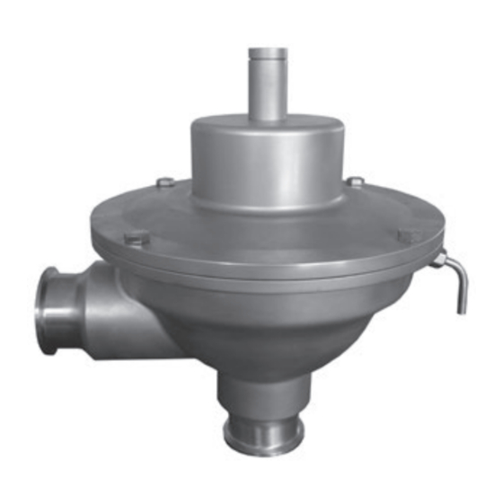
Type 2371-11 Pressure Reducing Valve
Type 2371-10 Pressure Reducing Valve
Manual set point adjustment
Pneumatic set point adjustment
Type 2371-10 Pressure Regulator · Pneumatic set point adjustment
Type 2371-11 Pressure Regulator · Manual set point adjustment
Series 2371 Pressure Reducing Valve for the Food and Pharmaceutical
Industries
Edition April 2020
Advertisement
Table of Contents

Related Manuals for Samson 2371 Series


Summary of Contents for Samson 2371 Series
- Page 1 EB 2640 EN Translation of original instructions Type 2371-11 Pressure Reducing Valve Type 2371-10 Pressure Reducing Valve Manual set point adjustment Pneumatic set point adjustment Type 2371-10 Pressure Regulator · Pneumatic set point adjustment Type 2371-11 Pressure Regulator · Manual set point adjustment Series 2371 Pressure Reducing Valve for the Food and Pharmaceutical Industries Edition April 2020...
- Page 2 Î For the safe and proper use of these instructions, read them carefully and keep them for later reference. Î If you have any questions about these instructions, contact SAMSON‘s After-sales Service Department (aftersalesservice@samsongroup.com). The mounting and operating instructions for the devices are included in the scope of delivery.
-
Page 3: Table Of Contents
Contents General safety instructions ................4 Process medium and scope of application ............5 Transportation and storage ................5 Design and principle of operation ..............6 Installation ....................10 Mounting orientation ..................10 Shut-off valve and pressure gauge ..............10 Safety valve ....................11 Leakage line connection ................11 Operation ....................11 Start-up .......................11 Adjusting the set point ..................11... -
Page 4: General Safety Instructions
General safety instructions General safety instructions − The regulator is to be mounted, started up or serviced by fully trained and qualified personnel only; the accepted industry codes and practices are to be observed. Make sure employees or third persons are not exposed to any danger. − All safety instructions and warnings given in these mounting and operating instructions, particularly those concerning installation, start-up, and mainte- nance, must be strictly observed. -
Page 5: Process Medium And Scope Of Application
Process medium and scope of application Process medium and scope 2.1 Transportation and storage of application The regulators must be carefully handled, transported and stored. During storage and Pressure regulators for the food and pharma- transportation before installation: Protect the ceutical industries for liquids and gases in the regulators against adverse influences, such as temperature range from 0 to 160 °C/32 to... -
Page 6: Design And Principle Of Operation
Design and principle of operation Design and principle of op- The set point is adjusted by an Allen key (8 mm), which is inserted through the adjust- eration ment opening (6.1) on top of the housing on- The Type 2371-10 and Type 2371-11 Pres- to the set point screw (6). The blanking plug sure Reducing Valves consist mainly of a sin- must first be removed. If necessary, the set gle-seated angle valve with operating dia-... - Page 7 Design and principle of operation The two diaphragms (4.1) provide a certain The screw (12) prevents parts from falling amount of safety when one of the diaphragms apart inadvertently while the regulator is be- ruptures and prevents the process medium ing dismantled.
- Page 8 Design and principle of operation Stem locking for CIP or SIP The pneumatic unit for the pneumatic stem locking is located on the top of the regulator. See section 6.1 on page 15. The unit can be mounted in any position since The Type 2371-10 and Type 2371-11 Regu- the axial fixture of the unit allows it to turn lators can be fitted with a stem locking to keep 360°.
- Page 9 Design and principle of operation Pneumatic stem locking Type 2371-10 To open the valve, apply a pressure p 1 bar) to the pneumatic unit. This causes the plug stem to move together with the plug out of the valve seat. A set point pressure p must not be applied to the regulator in this case. To switch the valve back to its control function, remove the pressure p (= 1 bar).
-
Page 10: Installation
Installation Installation 4.1 Mounting orientation The regulator has an angle-style NOTICE valve body. The actuator Pay particular attention to correct hygiene housing must face upwards. As and ensure that regulators for the food and a result, the outlet must face to pharmaceutical industries are kept absolutely the side in the installed position. -
Page 11: Safety Valve
Operation 4.3 Safety valve Operation The Type 2371-10 and Type 2371-11 Pres- 5.1 Start-up sure Reducing Valves are shut-off devices that do not guarantee absolute tight shut-off. First start up the regulator after mounting all When closed, these regulators can have a parts. leakage rate (see section 9 on page 26). Fill the plant slowly with the process medium. As a result, the output pressure p can rise to Avoid pressure surges. -
Page 12: Set Point · Type 2371-11
Operation 5.2.1 Set point · Type 2371- The valve closes when the output pressure p exceeds the pressure adjusted set point. 5. Retighten the locking screw (12) to prevent Manual set point adjustment ∙See Fig. 1 on the set point screw (6) from being turned. page 7. − Reinsert the stopper. The set point is adjusted for the lowest output pressure in the delivered state. - Page 13 Operation Stopper ∙ Locking screw (12) concealed Position of the locking screw (12) with stopper Fig. 4: Set point adjustment of Type 2371-11 EB 2640 EN...
-
Page 14: Set Point · Type 2371-10
Operation 5.2.2 Set point · Type 2371- G ¼ connection for the set point pressure line at the side on the pressure unit Pneumatic set point adjustment ∙ See Fig. 1 on page 7. How to proceed: 1. Connect the external set point pressure line at the G ¼ connection. Max. pressure = 8 bar. 2. Adjust the set point pressure p to obtain and keep the required pressure constant. Monitor the downstream pressure at a pres- sure gauge (see Fig. 3 on page 10). -
Page 15: Cleaning And Maintenance
Cleaning and maintenance Cleaning and maintenance 6.1 Cleaning The pressure reducing valves do not require To clean inside the regulator, the plug can be any maintenance. Nevertheless, they are sub- kept in the open position in the version with ject to natural wear, particularly at the seat, stem locking. - Page 16 Cleaning and maintenance Manual stem locking Type 2371-11 See ‘Stem locking for CIP or SIP’ on page How to proceed: 1. Remove the blanking plug and screw the pin (13) of the stem locking with the lock nut (14) into the adjustment opening. −...
- Page 17 Cleaning and maintenance Pneumatic stem locking Stem locking engaged = 6 bar Type 2371-10 and Type 2371-11 See section ‘Stem locking for CIP or SIP’ on connection page 8. Actuator housing Stem locking Type 2371-11 The pressure p = 6 bar applied to the pneu- matic unit opens the valve. This causes the plug stem to move together with the plug out of the valve seat and opens the valve.
- Page 18 Cleaning and maintenance Type 2371-10 Stem locking disengaged = Atmospheric pressure To open the valve, apply a pressure p 1 bar to the pneumatic unit. This causes the plug stem to move together with the plug out of the valve seat. A set point pressure p must connection not be applied to the regulator in this case. Actuator housing Stem locking How to proceed:...
-
Page 19: Maintenance · Replacing Parts
Cleaning and maintenance 6.2 Maintenance · Replacing 3. Prior to installing a new plug: Check the seat and seat facing, so far as it is possi- parts ble, for damage. In case of damage, the See Fig. 1 on page 7. regulator must be replaced or repaired. The regulator is subject to natural wear. - Page 20 Cleaning and maintenance concave sides facing away from each other (as shown in the drawing). − Do not forget the PEEK seal! Tightening torque − DN 15 to 25: 5 Nm Retaining (NPS ½ to 1) washers PEEK seal − DN 32 to 50: 20 Nm (NPS 1¼ to 2) Insert washers as shown in the diagram. Type 2371-11 ∙ Inserting the washers O-ring V-port plug with EPDM soft seal...
-
Page 21: Replacing The Diaphragm Unit
Cleaning and maintenance 6.4 Replacing the diaphragm Contact SAMSON if you intend to replace just the diaphragm or plug support. unit Type 2371-11 · Diaphragm unit How to proceed: In the event that the diaphragm is defective, See Fig. 11 we recommend replacing the entire dia- 1. -
Page 22: Replacing The Two Diaphragms
Cleaning and maintenance Note The plug stem is guided by ball bearings in the guide flange. On pulling off the guide flange, the ball bearings embedded in food grade lubricant are exposed and might fall out. 6. Carefully pull off the guide flange (5). Take the ball bearings out of the guiding grooves and keep them at hand for the following assembly. - Page 23 Cleaning and maintenance How to proceed: Note 1. Undo and remove the four screws (16, The plug stem is guided by ball bearings in width across flats 13). Keep in a safe the cover (valve bonnet). On pulling off the place for later.
-
Page 24: Replacing The Set Point Springs
SAMSON How to proceed: website (u www.samsongroup.com), in all The regulator does not need to be removed SAMSON product catalogs or on the back of from the pipeline. these Mounting and Operating Instructions. See section 6.4 on page 21, items 2 and 3. -
Page 25: Nameplate
Nameplate Nameplate The specifications are located on the actuator housing. art. 3 sect. 3 Made in France Fig. 16: Inscription field 2 on the housing Fig. 15: Inscription field 1 on the housing Comments: Mark of conformity (food) Comments: 10 PED labeling 11 Made in France/year of manufacture 12 Type designation 12 Arrow indicating the direction of flow Modification index Valve size DN Material numbers according to DIN EN... -
Page 26: Technical Data
Technical data Technical data Table 1: Technical data · All pressures (gauge) Type 2371-10/-11 Valve size DN 15 DN 20 DN 25 DN 32 DN 40 DN 50 10 0.5 to 6 bar Type 2371-10 – 2.5 to 2.5 to Set point ranges 16 – 6 bar 6 bar Type 2371-11 0.4 to 1.2 bar ∙ 1 to 3 bar ∙ 2.5 to 4.5 bar ∙ 4 to 6 bar Maximum pressure 10 bar Operating temp. -
Page 27: Dimensions
Dimensions 10 Dimensions 52 mm 7 mm Type 2371-11 ∙ Standard version Type 2371-11 ∙ With manual stem locking ØD 10.5 mm Refer to tables starting with Table 2 on page 29 for associated dimensions. Type 2371-11 with clamp end connections is shown in these drawings. The clamp fitting (connection between the actuator housing and valve) is turned 90° in the drawing. Type 2371-11 ∙ With pneumatic stem locking Fig. 17: Dimensional drawings for Type 2371-11 EB 2640 EN... - Page 28 Dimensions ØD 10.5 mm 41.3 mm Type 2371-10 ∙ Standard version Type 2371-10 ∙ With pneumatic stem locking Øint Øext Øint Øext L1 (L2) L1 (L2) Clamp connections Flanges Øint Øext Øint Øext L1 (L2) L1 (L2) Threaded connection according to DIN ... Threaded connection according to ISO/SMS ... Fig. 18: Dimensional drawings · Type 2371-10, various types of connection for Types 2371-10/-11 EB 2640 EN...
- Page 29 Dimensions Table 2: Dimensions of the regulators · All dimensions in mm Type 2371-11 Type 2371-10 DN 15 DN 20 DN 25 DN 32 DN 40 DN 50 DN 32 DN 40 DN 50 Valve size NPS ½ NPS ¾ NPS 1 NPS 1¼ NPS 1½ NPS 2 NPS 1¼ NPS 1½ NPS 2 Common dimensions ØD Weight, approx. Type 8.5 kg/19 lb 11 kg/24.3 lb 15 kg/33 lb...
- Page 30 Dimensions Table 3: Threaded connections · All dimensions in mm Type 2371-11 Type 2371-10 DN 15 DN 20 DN 25 DN 32 DN 40 DN 50 DN 32 DN 40 DN 50 Valve size NPS ½ NPS ¾ NPS 1 NPS 1¼ NPS 1½ NPS 2 NPS 1¼ NPS 1½ NPS 2 10 bar/150 psi DIN 11864-1 GS form A Series A Øint Øext RD34x1/8“ RD44x1/6“ RD52x1/6“ RD58x1/6“ RD65x1/6“ RD78x1/6“ RD58x1/6“ RD65x1/6“ RD78x1/6“ 10 bar/150 psi DIN 11864-1 GS form A...
- Page 31 Dimensions Table 4: Clamp connections · All dimensions in mm Type 2371-11 Type 2371-10 DN 15 DN 20 DN 25 DN 32 DN 40 DN 50 DN 32 DN 40 DN 50 Valve size NPS ½ NPS ¾ NPS 1 NPS 1¼ NPS 1½ NPS 2 NPS 1¼ NPS 1½ NPS 2 10 bar/150 psi DIN 11864-3 NKS form A Series A Øint Øext 50.5 50.5 50.5 77.5 50.5 77.5 10 bar/150 psi...
- Page 32 Dimensions Table 5: Flanges · All dimensions in mm Type 2371-11 Type 2371-10 DN 15 DN 20 DN 25 DN 32 DN 40 DN 50 DN 32 DN 40 DN 50 Valve size NPS ½ NPS ¾ NPS 1 NPS 1¼ NPS 1½ NPS 2 NPS 2 NPS 1¼ NPS 1½ 10 bar/150 psi DIN 11864-2 NF form A, Series A Øint Øext 10 bar/150 psi DIN 11864-2 NF form A, Series B Øint...
- Page 33 EB 2640 EN...
- Page 34 EB 2640 EN...
- Page 35 EB 2640 EN...
- Page 36 EB 2640 EN SAMSON AKTIENGESELLSCHAFT Weismüllerstraße 3 · 60314 Frankfurt am Main, Germany Phone: +49 69 4009-0 · Fax: +49 69 4009-1507 samson@samsongroup.com · www.samsongroup.com...
Need help?
Do you have a question about the 2371 Series and is the answer not in the manual?
Questions and answers