
Related Manuals for Challenge MPPHA-07CRN7-QB6


Summary of Contents for Challenge MPPHA-07CRN7-QB6
- Page 1 7000 BTU Air Conditioning Unit Model No. MPPHA-07CRN7-QB6 Care & Instruction Manual For household and indoor use only Please read these instructions before use and retain for future reference...
-
Page 2: Table Of Contents
Safety Page Explanation of symbols Electrical safety Warnings Battery warning Parts Main unit Operational panel Remote control Remote control display Accessories & fittings supplied Installation General Wall installation Continuous water drainage Fitting the batteries in the remote Operation General Basic operation – main unit Basic operation –... -
Page 4: Electrical Safety
Electrical safety You should only plug the appliance into a 220V‐240V AC, 50Hz supply. Connecting it to other power sources may damage the appliance and will invalidate the guarantee. Switch off and unplug when not in use and before cleaning or servicing the appliance. -
Page 5: Warnings
Warning! This appliance is intended exclusively for use in domestic households. It is not suitable for commercial use. Store in a cool, well ventilated room that has no continuously operating ignition source (e.g. open flames, operating gas appliance or electric heater) with a floor area larger than m ... -
Page 6: Battery Warning
Battery warnings CAUTION – Danger of explosion if batteries are incorrectly fitted / replaced. Batteries should be installed by an adult. Keep new and used batteries away from children. Only use ‘AAA’ 1.5V batteries in this remote control. ... -
Page 7: Parts
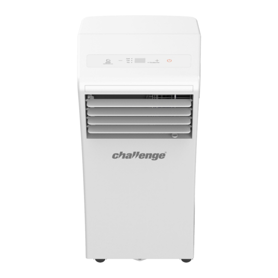
Parts Main unit 1. Operation panel 8. Carry handles 2. Remote control sensor 9. Air filter (behind grille) 3. Horizontal louvres 10. Upper air intake 4. Cold air outlet 11. Upper drain outlet 5. Vertical louvre lever 12. Air outlet 6. -
Page 8: Remote Control
Remote control... -
Page 9: Accessories & Fittings Supplied
Accessories supplied Accessories have been supplied for the unit to be vented via the wall. Wall adaptor – Wall adaptor – Unit adaptor Wall fixings part A part B Exhaust hose Drainage pipe... -
Page 10: Installation
Installation This unit is designed to be free standing and is required to be vented to the outside if being used in cooling (air conditioning) or auto modes. General The unit shall be installed, operated and stored in a room with a floor area larger than m ... -
Page 11: Wall Installation
complete the installation. The kits (CAT no.: 8763480) which are available for purchase from Argos. Venting through a wall This will require a hole to be drilled through the exterior property wall and additional parts to be purchased to complete the installation. If in doubt how to proceed, contact a builder or consult specialist literature. - Page 12 Slide the unit adaptor onto the rear of the air conditioning unit (fig. 2). Fig. 2 Decide of the location for the wall vent, the recommended height of the hole is between 30cm – 120cm above the floor (fig. 3). Fig.
- Page 13 Cut a 125mm hole through the wall. Fig. 4 Insert part B of the wall adaptor into the hole and using a pencil, mark the fixing points through the rim of the adaptor. Remove the adaptor and drill holes to a depth of 37mm.
-
Page 14: Continuous Water Drainage
Continuous water drainage Recommended for dry (dehumidifier) mode Ensure that unit is not connected to the mains supply. Unscrew and remove upper drain cap and remove the stopper. Keep in a safe place for future use. Fit the hose supplied and secure into position (fig. 5). Place the open end of the hose directly over the drain. -
Page 15: Operation
Operation General This air conditioner is suitable for use In room sizes 9 – 14m . Using in rooms above this size may make the conditioning effect less noticeable. With a room temperature below 35˚C. Operating the unit in room above this temperature will result in the unit stopping frequently and may result in damage. -
Page 16: Basic Operation - Main Unit
Basic operation - using the controls on the main unit Press the POWER pad to activate the unit. The unit will start operating and the display will activate. Press the MODE pad to select the desired mode. An indicator under the mode will illuminate to show which mode has been selected. -
Page 17: Timer Function
Notes: Ensure that curtains doors etc. do not block the signal between remote and receiver. Bright sunlight can interfere with an infrared signal and prevent it reaching the receiver. If this occurs, close a curtain near the unit to create shade. - Page 18 Setting timer on and timer off function in sequence Plug in the main unit and switch on at the mains. Select cool mode and set the desired room temperature. Press the TIMER ON button repeatedly until the desired switch on time interval is displayed on the screen.
-
Page 19: Sleep Function
Using the sleep function – cool mode only This function can help improve air conditioner energy use over the night time period. When sleep mode is activated the set temperature will increase by 1˚C after 30 minutes. After a further 30 minutes, it will increase again by 1˚C. -
Page 20: Maintenance
Maintenance Regular cleaning, maintenance and the correct storage will help ensure safe and efficient use and prolong the life of the product. General Switch off and disconnect from the mains supply before carrying out cleaning and maintenance. Keep the air vents and air conditioner surface free from dirt and clean the air filter regularly. -
Page 21: Draining The Collection Tray
Draining the collection tray Ensure that unit is not connected to the mains supply and disconnect the exhaust hose (if fitted). Move the unit to an area with a suitable drain (e.g. shower tray). Unscrew and remove the lower drain cap and remove the stopper (fig. 10). -
Page 22: Troubleshooting
Troubleshooting Observation Potential cause / solution Unit will not start Plug not fully inserted into the mains socket or not switched on P1 is displayed. Drain water in bottom tray Cooling mode - Room temperature lower than set temperature. Reset temperature Do you have a power cut? Room not cool Doors or windows in the room are not closed. -
Page 23: Technical Specification
Technical specification Challenge 7000 BTU Air Conditioning Unit Model MPPHA-07CRN7-QB6 Rated Voltage & Frequency 220 - 240V AC 50Hz Cooling capacity 7000BTU 2.0kW Dehumidifying capacity 1.94L/h Refrigerant Type R290 0 .14 k Weight Air flow volume 272m Timer Suitable for room size up to... -
Page 24: Plug Rewiring
Plug / Wiring advice The wires in this mains lead are coloured in accordance with the following UK electrical code: BLUE = NEUTRAL BROWN = LIVE GREEN + YELLOW = EARTH Non-rewireable plug This appliance may be fitted with a “non‐rewireable” plug. If you need to change the fuse in a “non‐rewireable”... -
Page 25: Warrant Y
Warrantee... -
Page 26: Information For Service Engineers
Information for service engineers Caution: Risk of fire / flammable Read the manual carefully materials Contains flammable refrigerant R290 Warning Do not use means to accelerate the defrosting process or to clean, other than those recommended by the manufacturer. ... - Page 27 Checks to the area Prior to beginning work on systems containing flammable refrigerants, safety checks are necessary to ensure that the risk of ignition is minimised. For repair to the refrigerating system, the following precautions shall be complied with prior to conducting work on the system. Work procedure Work shall be undertaken under a controlled procedure so as to minimise the risk of a flammable gas or vapour being present while the work is being...
- Page 28 No ignition sources No person carrying out work in relation to a refrigeration system which involves exposing any pipe work that contains or has contained flammable refrigerant shall use any sources of ignition in such a manner that it may lead to the risk of fire or explosion.
- Page 29 Checks to the refrigeration equipment Where electrical components are being changed, they shall be fit for the purpose and to the correct specification. At all times the manufacturer's maintenance and service guidelines shall be followed. If in doubt consult the manufacturer's technical department for assistance. The following checks shall be applied to installations using flammable refrigerants: ...
- Page 30 Repairs to sealed components During repairs to sealed components, all electrical supplies shall be disconnected from the equipment being worked upon prior to any removal of sealed covers, etc. If it is absolutely necessary to have an electrical supply to equipment during servicing, then a permanently operating form of leak detection shall be located at the most critical point to warn of a potentially hazardous situation.
- Page 31 Detection of flammable refrigerants Under no circumstances shall potential sources of ignition be used in the searching for or detection of refrigerant leaks. A halide torch (or any other detector using a naked flame) shall not be used. Leak detection methods The following leak detection methods are deemed acceptable for systems containing flammable refrigerants.
- Page 32 Removal and evacuation When breaking into the refrigerant circuit to make repairs or for any other purpose conventional procedures shall be used. However, it is important that best practice is followed since flammability is a consideration. The following procedure shall be adhered to: ...
- Page 33 Charging procedures In addition to conventional charging procedures, the following requirements shall be followed. Ensure that contamination of different refrigerants does not occur when using charging equipment. Hoses or lines shall be as short as possible to minimise the amount of refrigerant contained in them. ...
- Page 34 g) Start the recovery machine and operate in accordance with manufacturer's instructions. h) Do not overfill cylinders. (No more than 80 % volume liquid charge). Do not exceed the maximum working pressure of the cylinder, even temporarily. When the cylinders have been filled correctly and the process completed, make sure that the cylinders and the equipment are removed from site promptly and all isolation valves on the equipment are closed off.
- Page 35 Recovery When removing refrigerant from a system, either for servicing or decommissioning, it is recommended good practice that all refrigerants are removed safely. When transferring refrigerant into cylinders, ensure that only appropriate refrigerant recovery cylinders are employed. Ensure that the correct number of cylinders for holding the total system charge is available.
- Page 36 If you encounter any problems with this product please call our customer care team on 0345 640 20 20 Produced in China. Argos Limited, 489-499 Avebury Boulevard, Milton Keynes, MK9 2NW. Argos(N.I.)Ltd. Forestside Shopping Centre. Upper Galwally, Belfast, United Kingdom, BT8 6FX. Argos Distributors (Ireland) Limited, Unit 7, Ashbourne Retail Park, Ballybin Road, Ashbourne, Country Meath, Ireland...
Need help?
Do you have a question about the MPPHA-07CRN7-QB6 and is the answer not in the manual?
Questions and answers