
Related Manuals for MREL BLASTER'S RANGER II RAII-TS5-0


Summary of Contents for MREL BLASTER'S RANGER II RAII-TS5-0
- Page 1 Operations Manual RAII-TS5-0 Model Edition 2.8 MREL GROUP OF COMPANIES LIMITED 5-779 Sir John A MacDonald Blvd. Kingston, Ontario K7L 1H3 Canada T: +1-613-545-0466 E: contact@mrel.com www.mrel.com...
- Page 2 Copyright Information MREL Group of Companies Limited (MREL) warrants that the product is free from Manufacturer’s defects for a period of one (1) year from the date of shipment to the Customer. This Warranty covers all parts and labour. MREL does not warrant that the product will meet the Customer’s requirements, or that it will operate in the combinations which may be selected by the Customer.
-
Page 3: Table Of Contents
Camera Setup 3.5.1 Blaster’s Ranger II™ Setup 3.5.2 Mount the F-Mount Zoom Lens to the Camera 3.5.3 Blaster’s Ranger II™ I/O Cable and Trigger Switch Cable 3.5.4 DC Power Connection Camera Display and Menu Navigation Buttons T: +1-613-545-0466 www.mrel.com contact@mrel.com... - Page 4 Using the Touchscreen 3.7.1 To Enable the Touchscreen 3.7.2 Calibration 3.7.3 To Calibrate the Touchscreen Controlling the Displays 3.8.1 HDMI Display Blaster’s Ranger II™ Name the Camera 3.9.1 Camera Name 3.10 Setting the Time 3.10.1 Setting the Time Manually 3.10.2 Setting the Time via NTP 3.11 Storage Setup...
- Page 5 Under the Tracking Box 7.2.8 Save All Toolkits Excel Spreadsheet - Mining_Demo.xls 7.3.1 Explanation of the Unshaded Cells Example Demonstration File Explanation - Disrupter Example 7.4.1 Image Processing 7.4.2 Multi-Plane Calibration 7.4.3 Display Layers 7.4.4 Notes T: +1-613-545-0466 www.mrel.com contact@mrel.com...
- Page 6 Save All Toolkits Excel Spreadsheet - ProAnalyst_Demo.xls 7.5.1 Explanation of the Unshaded Cells Chapter 8: Contacting MREL for Technical Support Contacting MREL Appendix A: Definition of Terms Appendix B: Blaster’s Ranger II™ Specifications B la ste r ’s R a n g er II Op er a tio ns Ma nua l - E d i ti on 2 .8...
-
Page 7: Chapter 1 Introduction
Chapter 1 Introduction T: +1-613-545-0466 www.mrel.com contact@mrel.com... -
Page 8: Introduction
Over view This Chapter provides an introduction to high speed photography and to high speed photography of blasts. 1.1 Introduction Congratulations on your purchase of a Blaster’s Ranger II™ High Speed Digital Camera. This Operations Manual provides instructions on the use of the hardware supplied with the Blaster’s Ranger II™... - Page 9 With high speed digital video photography, many of these phenomena and occurrences can now be observed “as they happen”. “High Speed Photography in Open Pit Blasting” by Mining Resource Engineering Limited. March 1983. ISBN 0-9691314-0-2. Available from the International Society of Explosives Engineers (www.isee.org). T: +1-613-545-0466 www.mrel.com contact@mrel.com...
- Page 10 B la ste r ’s R a n g er II Op er a tio ns Ma nua l - E d i ti on 2 .8...
-
Page 11: Chapter 2 Hardware
Chapter 2 Hardware T: +1-613-545-0466 www.mrel.com contact@mrel.com... -
Page 12: Blaster's Ranger Ii™ High Speed Digital Video Camera
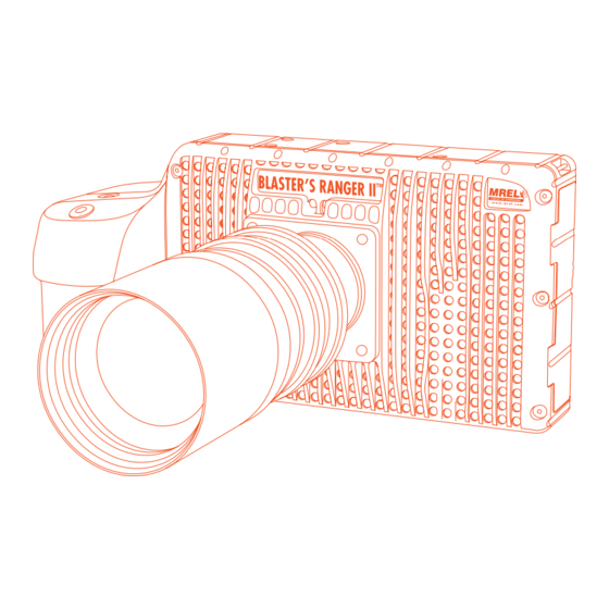
Over view This Chapter describes all of the hardware components provided with the Blaster’s Ranger II™ High Speed Digital Camera. 2.1 Blaster’s Ranger II™ High Speed Digital Camera Blaster’s Ranger II™ High Speed Digital Camera is encased in a rigid anodized aluminum housing. The housing is sealed to resist dirt and moisture and is equipped with many connection ports: the Ethernet Communication port and the... -
Page 13: Camera Bottom
2.1.3 Camera Back Trigger Button USB port Battery Status LED Sync Activity LED Camera Status LED Power LED Network Activity LED Storage Activity LED Touch-Screen Display Display Button Menu Button D-Pad Arm Button Power ON/OFF Button T: +1-613-545-0466 www.mrel.com contact@mrel.com... -
Page 14: Camera Input Output Panel
2.1.4 Camera Input Output Panel USB OTG (Micro A/B connector) SDHC Port GigE Port (R J45 connector) Sync I/O, Trigger (Lemo connector) HDMI Port (Type A connector) DC Power In (Lemo connector) 2.2 BLASTER’S RANGER II™ ACCESSORIES 2.2.1 Protective Carry Case Carry Case is designed to contain, for transportation and storage all the components required for setup and use of the... -
Page 15: Blaster's Ranger Ii™ Dc Power Cable
The trigger cable with switch allows the user to trigger the camera at a distance. The user can extend this cable with the appropriate BNC connectors and a reel of RG-58 coaxial cable. 2.2.8 SD Card Blaster’s Ranger II™ is shipped with a 16GB high performance Card. T: +1-613-545-0466 www.mrel.com contact@mrel.com... -
Page 16: Usb Communication Cable
2.2.9 USB Communication Cable It is a USB-A to USB-Micro-B cable. Once connected via the Blaster’s Ranger II™ port to a PC, any mass storage device on the camera can be accessed by the PC. This includes an SD Card, Solid State Drive, or thumb drive in the USB port. 2.2.10 ProAnalyst®... -
Page 17: Chapter 3: Getting Started
Chapter 3 Getting Started T: +1-613-545-0466 www.mrel.com contact@mrel.com... -
Page 18: Introduction
Over view This chapter provides an outline of how to setup the Blaster’s Ranger II™. This chapter assumes that the user will first want to unpack the Blaster’s Ranger II™ and set it up in an office environment in order to learn the camera controls. 3.1 Introduction This chapter provides a detailed description of the setup procedure for the Blaster’s Ranger... -
Page 19: Attaching The External Power Supply
/ charging menu. The power up / charging menu is showed below. “Slow SSD” means that writes to the SSD will be at about 240MB/sec, while “Fast SSD” bumps the write speed up to 480MB/sec. T: +1-613-545-0466 www.mrel.com contact@mrel.com... -
Page 20: Mass Storage
It is highly recommended that you use an external power supply such as an AC adapter or battery belt when using “Fast SSD” mode. At the power up / charging menu, select “Camera On” to boot the camera. If you do nothing, the camera will proceed to charge the battery. -
Page 21: Blaster's Ranger Ii™ Solid State Drives (Internal Ssd)
PC using a USB-A to USB-Micro-B cable. Once connected via the Blaster’s Ranger II™ OTG port, any mass storage device on the camera can be accessed by the PC. T: +1-613-545-0466 www.mrel.com contact@mrel.com... -
Page 22: Camera Setup
This includes an SD Card, Solid State Drive, or thumb drive in the port. To use this option: Power up the Blaster’s Ranger II™. Install thumb drive and/or SD Card in the camera. Attach the camera to the PC via the camera’s USB-OTG port, which is next to the SD Card slot... -
Page 23: Mount The F-Mount Zoom Lens To The Camera
When the camera powers on for the first time, the default display is a live image with no menu displayed. Pressing the Display (DISP) Button while toggles the LCD between three modes: Display off; Display on; Display on with Histogram. T: +1-613-545-0466 www.mrel.com contact@mrel.com... - Page 24 When there is captured video to review, a mode with playback controls is added. Menu Button toggles the on screen menus on and off. While navigating menus, the Menu button is used to go backward through levels of the menu. For example, if you are navigating a Menu pressing the Menu button will return you to the Menu...
-
Page 25: Using The Touchscreen
(This is there to prevent you from accidently calibrating the touchscreen while handling the camera.) The Calibration screen, Figure 10: Touchscreen Calibration, will appear and prompt you to touch a cross hair at each corner of the screen, then in the center. T: +1-613-545-0466 www.mrel.com contact@mrel.com... -
Page 26: Controlling The Displays
3.8 Controlling the Figure 11: Display Controls Displays There are three menu elements in the Display menu that control the behavior of the displays. These are: • LCD Dimmer • Backlight control • HDMI LCD Dimmer is a timer that turns the LCD display off after a number of minutes. -
Page 27: Blaster's Ranger Ii™ Name The Camera
There are many symbols available on the keypad that are not valid for camera naming. If you enter symbols that are not usable, those characters and any subsequent characters will be stripped from the camera name as soon as you navigate away from the Name Menu. Figure 14: Alphanumeric Dialog Box T: +1-613-545-0466 www.mrel.com contact@mrel.com... -
Page 28: Setting The Time
3.10 Setting the Time Figure 15: Time Format Menu Time Setup on the Blaster’s Ranger II™ is located in the System Menu. There are two choices for setting the time of the camera: User NTP. If you select User, the time and date are manually entered into the camera. -
Page 29: Configuration And Camera Information
(Configuration #1, or #2) Select Reset to load the factory default configuration. General information about the camera, including MAC address and versions of software, FPGA, Sensor and Gig-E are available in Information in the System Menu. T: +1-613-545-0466 www.mrel.com contact@mrel.com... - Page 30 B la ste r ’s R a n g er II Op er a tio ns Ma nua l - E d i ti on 2 .8...
-
Page 31: Chapter 4: Operation Of The Blaster's Ranger
Chapter 4 Operation of the Blaster’s Ranger II™ T: +1-613-545-0466 www.mrel.com contact@mrel.com... -
Page 32: Selecting The Recording Mode
Over view This chapter provides an outline of how to setup the Blaster’s Ranger II™ for recording, viewing, and saving events. 4.1 Selecting the Recording Mode Blaster’s Ranger II™ cameras record to internal high-speed DRAM memory. With up to 8GB of memory available, maximum recording times for Blaster’s Ranger II™... -
Page 33: Long Recording Modes (Optional)
All recordings are available for playback on one timeline. Use Record Start markers to jump between the recordings during playback. Now you can save the videos or the interesting part video to the SD card or a USB card inserted in the camera. Autosave is not available. T: +1-613-545-0466 www.mrel.com contact@mrel.com... -
Page 34: Setting Frame Rate And Resolution
Note: If you wish to stop recording before all of the post-Trigger frames are recorded, you may cancel the recording by pressing Arm, then select to “Retain the current session” 4.2 Setting Frame Rate and Resolution Frame rate and resolution are set together as they are interactive. The maximum frame rate of the camera is based on its resolution as seen Table 5: Frame Rates and Resolutions, below. -
Page 35: Aliasing And Frame Rate
Lets say, for example, that you have captured images at 1024 x 1024 @ 500fps and are now interested at capturing a 512 x 512 portion of the scene, lets say the bottom right hand quarter @ 2000fps. T: +1-613-545-0466 www.mrel.com contact@mrel.com... -
Page 36: Binning And Subsampling On The Blaster's Ranger
In this case, you would wish to add 512 to both the X and Y offset. For a 1024 x 1024 centered image the offsets will be 128 and 0. The resultant offsets for a 512 x 512 image (lower right quadrant) would be 740 and 512. 4.3 Binning and Subsampling on the Blaster’s Ranger II™... -
Page 37: Setting Shutter Speed
Setting the ƒ-stop to a lower value (more open iris) reduces the depth of focus, while setting the exposure to a higher value (longer exposure) increases motion blur. 4.5 Low Light Mode There is an option labeled “Low Light.” THIS IS NOT A SHUTTER SPEED USED FOR RECORDING! This does cause a lot of issues with customers. T: +1-613-545-0466 www.mrel.com contact@mrel.com... -
Page 38: Low Light Mode
This is a special shutter speed that works in “Live Mode” only - for Live view and not while recording. In some special circumstances, the light available for setting up the Blaster’s Ranger II™ for a high-speed event is not the same as what will be used for event itself. -
Page 39: Configuring The Trigger
If Disabled, click on the “Disabled” button. It will turn green and the text will change to “Enabled.” The next button to the right will either say Rising or Falling Edge. If you need to change the setting, click on this button to open the dialog box. T: +1-613-545-0466 www.mrel.com contact@mrel.com... - Page 40 Figure 21: Trigger Position For use with the supplied trigger switch, the Blaster’s Ranger II™ should be set to Falling Edge. See Figure The external trigger is one of six external I/O connections available on the camera. Each of these may be used in one of two ways: 1.
-
Page 41: Black Level Calibration
II™’s sensor. It does not do as good a job cleaning up the images as Column FPN Blaster’s Ranger Pixel FPN. FPN Off means that there is no noise correction being used. T: +1-613-545-0466 www.mrel.com contact@mrel.com... -
Page 42: Record: Arm And Trigger
4.9 Record: Arm and Trigger • Dark Level Calibration has been done • The scene is framed and focused • Resolution Frame Rate are set • Shutter Speed is set • Bit Depth is set • Trigger Point Trigger Type is set Figure 24: Camera LED 4.9.1 Take a Still JPEG... -
Page 43: Trigger
“0” and the post-trigger frames. The progress bar will change color and move from the trigger point to the end as in the three images below. When the recording is complete, the progress bar will turn solid green. T: +1-613-545-0466 www.mrel.com contact@mrel.com... -
Page 44: Autosave
Figure 26: Recording Progress: Triggered Blaster’s Ranger II™ Blaster’s Ranger II™ will now either enter Review Mode or, if Autosave has been enabled, the camera will save the images to a mass storage device and go back to Armed Mode, capturing pre-trigger frames and watching for a Trigger. -
Page 45: To Set Up Autosave
The camera will operate in FasFire mode whenever there are at least two FasFire partitions and the camera is set to AutoSave. In FasFire, as soon as the camera receives an Arm signal, FasFire will commence. T: +1-613-545-0466 www.mrel.com contact@mrel.com... -
Page 46: Using The Gas Gauge
4.11.2 Using the Gas Gauge Using the DISP button on the Blaster’s Ranger II™ to toggle through the displays in FasFire, you will find that there is a “gas gauge” available at the upper left corner of the image. When the gas gauge is solid green, as in the upper image on the previous page, all memory partitions are empty. This means that either you have not triggered the camera yet, or that all of the partitions you have recorded have been saved. - Page 47 (up to 128) to be inserted in the recording timeline. It is possible to alternate FasCorder ROC and BROC recordings in any combination as they are compatible formats. Long Record basic recordings, however, are not compatible with FasCorder and cannot coexist on the SSD. T: +1-613-545-0466 www.mrel.com contact@mrel.com...
-
Page 48: Reviewing Captured Imagery: Playback
4.13 Reviewing Captured Imagery: Playback Once the recording is complete, if Autosave is not enabled, the Blaster’s Ranger II™ will open the recording in Review Mode. There are three things to do in Review: Play the video-play it forward, backward, frame by frame, adjust the cut-in and cut-out points (find the interesting portion of the clip), etc. -
Page 49: Image Processing
If you have recorded 10-bit images, a menu item for Bit Depth will also be present in the Display Menu. If 8-bit images have been recorded, the bit selection has already been made, so this menu does not appear. T: +1-613-545-0466 www.mrel.com contact@mrel.com... -
Page 50: Saving Images To Mass Storage
NOTE: Making a selection from this menu only affects the Displayed image and any (non RAW) images saved to a mass storage device. It does not affect the either the 8-bit 10-bit images as they are recorded into the Blaster’s Ranger II™’s high-speed internal memory. - Page 51 Image files may be saved multiple times using different formats, different start and stop points, and different image processing options (brightness, contrast, gamma, color, etc.). If 10-bit images have been captured, imagery may be saved multiple times using different bit-depths. T: +1-613-545-0466 www.mrel.com contact@mrel.com...
-
Page 52: Sync In
4.16 Sync In is easily synchronized to an external device such as another camera, or a precision timing generator. Blaster’s Ranger II™ 4.16.1 Per Frame “Per Frame” option is used when you wish the camera to capture at a rate of one sync-pulse per frame or greater. To set up Sync-In: Navigate to the Control... -
Page 53: Sync Out
Sync Out Pass Sync In Sync Sync In option, which simply inverts the signal. 4.18 Master/Slave Setup There are many possible configurations used to synchronize groups of cameras. The Master/Slave configuration is often used when a T: +1-613-545-0466 www.mrel.com contact@mrel.com... - Page 54 group cameras is used to capture multiple Figure 34: Master and Slave Cameras synchronous views of an event that is not driven by a clock or PLC. For example, when SYNC IN TRIGGER studying animal or human kinetics, the subject SYNC OUT (animal or human) is not supplying a sync signal for the camera system, so the camera...
-
Page 55: Chapter 5: Field Operations
Chapter 5 Field Operations T: +1-613-545-0466 www.mrel.com contact@mrel.com... -
Page 56: Introduction
Sensor Fusion™ Combinatory analysis of video data with VOD data or other sensors allows live visualization of issues perceived from other data acquisition methods such as those captured by the MREL DataTrap II™ MREL MicroTrap™. The Figure on the following page illustrates the various high speed video photography applications. - Page 57 Figure 35: High Speed Photography Application T: +1-613-545-0466 www.mrel.com contact@mrel.com...
-
Page 58: Selecting A Camera Position
Make Trigger wrapped over the end of a detonator). If the User intends to trigger the recording manually, the push-button trigger device is available from MREL with any desired length of cabling. Finally, the location should also ensure that during the blast, the first boreholes to fire do not obscure the line of sight of other boreholes. -
Page 59: Power Supply Option
Review Mode. 13. Click on the Live button to put the camera back into Live Mode. From here a new recording can be made or the camera’s configuration can be changed. T: +1-613-545-0466 www.mrel.com contact@mrel.com... - Page 60 I M P O R T A N T The Blaster’s Ranger II™ Camera image memory is volatile memory and images will be lost if a new recording is initiated or the Blaster’s Ranger II™ Camera is powered off . Be sure to save important videos before initiating a new recording or turning off the Blaster’s Ranger II™...
-
Page 61: Chapter 6: Using The Blaster's Ranger Ii™ With A Pc
Chapter 6 Using the Blaster’s Ranger II™ with a PC T: +1-613-545-0466 www.mrel.com contact@mrel.com... -
Page 62: Connecting To A Pc Via Ethernet
Over view This Chapter provides the outline how to connect a PC to the Blaster’s Ranger II™. 6.1 Connecting to a PC via Ethernet Figure 36: Attaching the Ethernet Cable Blaster’s Ranger II™ may be connected to a PC using the USB-OTG connection, (Refer Section... -
Page 63: Autoconfiguration
Type the camera’s IP address or camera name into the browser’s Location bar. A camera control application within the camera does the rest. A control menu will appear in your browser that will give a live camera view and complete control over the camera operation. T: +1-613-545-0466 www.mrel.com contact@mrel.com... - Page 64 B la ste r ’s R a n g er II Op er a tio ns Ma nua l - E d i ti on 2 .8...
-
Page 65: Chapter 7: Proanalyst Introductor Y Edition Software
Chapter 7 ProAnalyst Introductory ® Edition Software T: +1-613-545-0466 www.mrel.com contact@mrel.com... -
Page 66: About Proanalyst ® Introductory Edition
32 features. Will allow the User to ProAnalyst Introductory Edition ® quickly export to Excel or Matlab for further analysis and graphing. If you need to track more than one point at the same time, please contact MREL to upgrade to ProAnalyst Professional Edition. ProAnalyst... -
Page 67: Image Processing
After the two points are selected, the user can enter the value between the two points selected and then select the units of measurement of the number from the pull down menu. After the units are selected, the Apply Scale >> button MUST be clicked. This will change the box beside the button to xx pixels/“units selected”. T: +1-613-545-0466 www.mrel.com contact@mrel.com... -
Page 68: Display Layers
The origin of the coordinate system can be set in a similar method. Point the reticle to point were the operator requests the coordinate origin to be (0,0). This will be the reference point for all of the measurements. After the origin is set, the orientation of the axes must be set. - Page 69 7.2.6.1 Show All Display every point created. 7.2.6.2 Show Past Display only past point created in the video. 7.2.6.3 Show Current Display only the current point. 7.2.6.4 Show None This will not display any points. T: +1-613-545-0466 www.mrel.com contact@mrel.com...
-
Page 70: Under The Tracking Box
7.2.7 Under the Tracking Box The buttons from left to right are: Track Backwards, Track One Frame Backwards, Stop, Track One Frame Forward Track Forward. The software takes an image of the Defined Region when the Set Region button is pressed. At some points, the Automatic Tracking loose the item of interest, the user MUST... -
Page 71: Explanation Of The Unshaded Cells
The Graphs tab has all of the measurements in a graphical solution. The graph on the left is the final solution produced by MREL to show the user what a completed graph could look like. The two white lines and text boxes were manually generated by hovering the cursor over the graph to record the values. This can be done on the graph on the right. -
Page 72: Example Demonstration File Explanation - Disrupter Example
7.4 Example Demonstration File Explanation – Disrupter Example This Mining example is for the purpose of learning ProAnalyst® Introductory Edition. The example file can be found in the Disrupter_ Demo directory. This example file was captured at 1000 frames per second. The calibration of the video is as shown in the calibration tab with the distance from the edge of the blue container to the third sensor (which is a third of the distance from the tip to the pole) is 5 meters. -
Page 73: Image Processing
The positive orientation of the two axes will be along the edge of the frame. For example, the top left button will set positive X direction to the right and the positive Y direction down while the bottom right button will set the T: +1-613-545-0466 www.mrel.com contact@mrel.com... -
Page 74: Display Layers
positive X direction to the left and the positive Y direction up. The four buttons around the reticle will set the positive orientation around the button pressed from the reticle position. If the orientation of the X axis is not horizontal, from the origin of the coordinate system place the reticle on the horizontal line and then click Set X Direction. -
Page 75: Under The Tracking Box
Region. The operator can then continue the track in the same direction (forward or backwards) and the previously tracked points will move to the new location. T: +1-613-545-0466 www.mrel.com contact@mrel.com... -
Page 76: Save All Toolkits
Once the object is tracked, the lock between the eye and the wrench should then be closed (to the locked position) to avoid and changes to the points. section will allow the user to select the units to export the data to as well as the form that the file will be. Units &... - Page 77 (-1) because the coordinate system was defined with Positive X to the right, the left side positive motion is to the left. The other solution is to define another calibration for the Left_Side measurement. All of the other measurements are as described above. The Graphs tab has all of the measurements in a graphical solution. T: +1-613-545-0466 www.mrel.com contact@mrel.com...
- Page 78 B la ste r ’s R a n g er II Op er a tio ns Ma nua l - E d i ti on 2 .8...
-
Page 79: Chapter 8: Contacting Mrel For Technical Support
Chapter 8 Contacting MREL for Technical Support T: +1-613-545-0466 www.mrel.com contact@mrel.com... -
Page 80: Contacting Mrel
Email: support@mrel.com Webpage Support: www.mrel.com/contact.html MREL looks forward to providing you with assistance. B la ste r ’s R a n g er II Op er a tio ns Ma nua l - E d i ti on 2 .8... -
Page 81: Appendix A: Definition Of Terms
(K). High color temperatures are seen bluish, while lower color temperatures are seen reddish. Config Camera Configuration that can be saved and reloaded. Includes settings for Frame Rate, Resolution, Shutter Speed, Trigger, bit depth, and Auto Save. T: +1-613-545-0466 www.mrel.com contact@mrel.com... - Page 82 Contrast Linear image control that enhances the difference between pixel values by changing the slope of the curve, while maintaining the mean value. Cursor The cursor may be any graphic indication of where the current focus is within the user interface. This may be anything from a blinking vertical line as used within a dialog box when the user is entering text, or it may be a change in the color of a button as when navigating through menus.
- Page 83 SSD drive within the camera, or remote, such as a PC. This is Secure Digital memory, such as the SD Card used as a plug-in mass storage device for the camera. T: +1-613-545-0466 www.mrel.com contact@mrel.com...
- Page 84 Solid-state drive that is located inside the camera. This is a non-volatile mass storage device retains its data when the camera is powered down. Static IP In order for one networked device to “talk” to each other, they need to have compatible IP addresses. One way to assure this is for the user to assign unchanging (static) IP addresses to each device.
-
Page 85: Appendix B: Blaster's Ranger Ii™ Specifications
Power Rechargeable Battery Pack – 3 hours, or 10-26 VDC external power supply Power Consumption 7.5 Watts maximum Operating Environment +5°C to +40°C 228mm W x 114mm H x 89mm D. 1.8 kg Size and Weight T: +1-613-545-0466 www.mrel.com contact@mrel.com... - Page 86 MREL is committed to product innovation; accordingly product may undergo specification improvements without notice. Copyright © 2022 MREL Group of Companies Limited. Blaster’s Ranger II™ High Speed Camera, Blaster’s Ranger II™ High Speed Camera Logo, and MREL Logo are trademarks or registered trademarks of MREL Group of Companies Limited.
Need help?
Do you have a question about the BLASTER'S RANGER II RAII-TS5-0 and is the answer not in the manual?
Questions and answers