Table of Contents
Advertisement
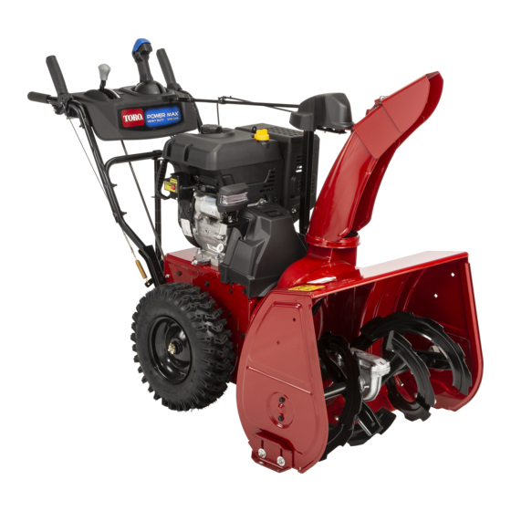
Power Max Heavy Duty 928 OE and 926/1028 OXE
Snowthrower
Model No. 38660—Serial No. 313000001 and Up
Model No. 38664—Serial No. 313000001 and Up
Model No. 38674—Serial No. 313000001 and Up
Introduction
This machine is intended to be used by residential
homeowners or professional, hired operators. It is
designed for removing snow from paved surfaces, such
as driveways and sidewalks, and other surfaces for
traffic on residential or commercial properties. It is not
designed for removing materials other than snow.
Read this information carefully to learn how to operate and
maintain your machine properly and to avoid injury and
machine damage. You are responsible for operating the
machine properly and safely.
You may contact Toro directly at www.Toro.com for machine
and accessory information, help finding a dealer, or to register
your machine.
Whenever you need service, genuine Toro parts, or additional
information, contact an Authorized Service Dealer or Toro
Customer Service and have the model and serial numbers of
your machine ready. Figure 1 identifies the location of the
model and serial numbers on the machine. Write the numbers
in the space provided.
© 2012—The Toro® Company
8111 Lyndale Avenue South
Bloomington, MN 55420
This manual identifies potential hazards and has safety
messages identified by the safety alert symbol (Figure 2),
which signals a hazard that may cause serious injury or death
if you do not follow the recommended precautions.
This manual uses 2 words to highlight information.
Important calls attention to special mechanical information
and Note emphasizes general information worthy of special
attention.
Register at www.Toro.com.
G016493
Figure 1
1. Model and serial number location
Model No.
Serial No.
Figure 2
1. Safety alert symbol
Original Instructions (EN)
All Rights Reserved *3373-560* B
Printed in the USA
Form No. 3373-560 Rev B
Operator's Manual
ST OP
1
Advertisement
Table of Contents


Need help?
Do you have a question about the Power Max Heavy Duty 928 OE and is the answer not in the manual?
Questions and answers