Table of Contents
Advertisement
Advertisement
Table of Contents

Related Manuals for A-iPower SUA4000i


Summary of Contents for A-iPower SUA4000i
- Page 1 SUA4000i 10887 Commerce Way Unit A Fontana CA 92337...
-
Page 3: Table Of Contents
Shutting Off the Generator .............22 Maintenance .................23 Transportation & Storage ...............28 Troubleshooting Guide ..............29 Wiring Diagram ................30 Exploded View & Parts List ............31 Warranty Statement ..............33 KEY SPECIFICATIONS Model NO. SUA4000i Starting Wattage 4000W Running Wattage 3500W Phase Single Frequency 60Hz... -
Page 4: Introduction
SAFETY INFORMATION WARNING: Before operating the generator, make sure to read all safety warnings and all instruc- tions. Failure to follow the warnings and instructions may result in electric shock, fire or serious injury. SAFETY INTRODUCTION Safety is a combination of common sense, staying alert, and knowing how your tool works. This manual contains important information regarding the generator’s potential safety concerns, as well as preparation, operation, and maintenance instructions. - Page 5 IMPORTANT SAFETY INSTRUCTIONS...
- Page 6 IMPORTANT SAFETY INSTRUCTIONS...
- Page 7 IMPORTANT SAFETY INSTRUCTIONS...
- Page 8 IMPORTANT SAFETY INSTRUCTIONS...
- Page 9 IMPORTANT SAFETY INSTRUCTIONS...
-
Page 10: Generator Safety Warnings
GENERATOR SAFETY WARNINGS DANGER: CARBON MONOXIDE Using a generator indoors CAN KILL YOU IN MINUTES. Generator exhaust contains carbon monox- ide (CO). This is a poison gas you cannot see or smell. If you can smell the generator exhaust, you are breathing CO. - Page 11 GENERATOR SAFETY WARNINGS WARNING: Do not let comfort or familiarity with the product replace strict adherence to product safety rules. Failure to follow the safety instructions may result in serious personal injury. OPERATING ENVIRONMENT 1. Using a generator indoors can kill you in minutes. Only use a generator OUTSIDE and far away from win- dows, doors and vents.
- Page 12 GENERATOR SAFETY WARNINGS GENERATOR OPERATION 1. Only use the generator for its intended purposes. Modifying or using the generator for operations for which it was not designed may cause hazards and personal injury. 2. Do not touch bare wires or receptacles (outlets). 3.
-
Page 13: Know Your Generator
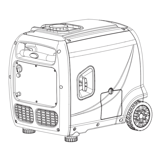
KNOW YOUR GENERATOR GENERATOR Fuel Cap Carrying Handle Telescopic Rod Control Panel Recoil Starter Oil Access Cover Wheel Foot Maintenance Cover Battery Access Cover Muffler... - Page 14 KNOW YOUR GENERATOR CONTROL PANEL 13 14 1. Fuel Switch 8. AC 120V NEMA 5-20 Duplex Receptacles (20A) 2. Choke 9. AC 120V NEMA L5-30 Receptacle (30A) 3. Parallel Operation Outlets 10. Engine Switch Connect two AIPOWER inverter generators 11. Low Idle Mode through a parallel connection kit for a higher Turn ON to increase fuel economy and runtime output...
- Page 15 KNOW YOUR GENERATOR LOW IDLE SWITCH This generator is equipped with an LOW IDLE Switch (Fig. 1). Engaging this switch allows the system to regulate the engine speed and automatically adjust its fuel consumption to match the required load. When the electrical load changes, the generator engine will automatically speed up and slow down as needed.
- Page 16 KNOW YOUR GENERATOR GENERATOR CAPACITY Make sure the generator can supply enough running (rated) and starting (max.) watts for the items you will power at the same time. Follow these simple steps. Select the items you will power at the same time. Total the running (rated) watts of these items.
- Page 17 KNOW YOUR GENERATOR The chart below serves as a reference for the estimated wattage requirements of common electrical de- vices. However, do not solely rely on this chart - all electronics and appliances are built differently. Always check the wattage listed on the electrical device before consulting this chart. Tool or Appliance Rated (Running) Watts Surge (Starting) Watts...
-
Page 18: Generator Preparation
GENERATOR PREPARATION The following section describes the necessary steps to prepare the generator for use. Failure to perform these steps properly can damage the generator or shorten its life. STEP 1 - ADD/CHECK OIL The generator is shipped without oil. User must add the proper amount of oil before operating the generator for the first time. - Page 19 GENERATOR PREPARATION For subsequent operation, the oil level should be checked before each use, or after every 8 hours of opera- tion. The generator is equipped with a low-oil sensor and will NOT start without a sufficient amount of oil. To check oil level (before every subsequent start): 1.
- Page 20 GENERATOR PREPARATION To add gasoline, follow these steps: 1. Make sure the generator is shut OFF and on a level Fuel Cap surface. Unscrew the fuel cap (Fig. 8) and set it aside. The fuel cap may be tight and hard to unscrew. 2.
-
Page 21: Starting The Generator
STARTING THE GENERATOR Before starting the generator, make sure you have read and performed the steps in the “Generator Prepara- tion” section of this manual. If you are unsure about how to perform any of the steps in this manual Please contact your authorized service center DANGER: CARBON MONOXIDE Using a generator indoors CAN KILL YOU IN MINUTES. - Page 22 STARTING YOUR GENERATOR Before starting the generator: 1. Verify that the generator is outside on a dry, level surface. Allow at least two feet of clearance on all sides of the generator. 2. To maximize safety, check that the generator is properly grounded (see “GROUND THE GENERATOR”). 3.
-
Page 23: Shutting Off The Generator
SHUTTING OFF THE GENERATOR CAUTION: Unplugging running devices can cause damage to the generator. Never stop the engine with electrical devices connected and running. 1. Turn off all electrical devices prior to unplugging them from the generator. Unplugging running devices can cause damage to the generator. 2. -
Page 24: Maintenance
MAINTENANCE RECOMMENDED MAINTENANCE SCHEDULE Proper routine maintenance of the generator will help prolong the life of the machine. Please perform maintenance checks and operations according to the Maintenance Schedule. If there are any questions about the maintenance procedures listed in this manual, Please contact your authorized service center. WARNING: Never perform maintenance operations while the generator is running. - Page 25 MAINTENANCE AIR FILTER MAINTENANCE Check every 50 hours of operation (refer to Recommended Maintenance Schedule). Routine maintenance of the air filter helps maintain proper airflow to the carburetor. Occasionally check that the air cleaner is free of excessive dirt. To inspect and clean the air filter: 1.
- Page 26 MAINTENANCE 4. Visually inspect the spark plug. If it is cracked or chipped, or if the electrodes are worn or burned, discard it and replace with a new spark plug. 0.7 - 0.8 mm 0.028 - 0.031 in. 5. If re-using the spark plug, use a wire brush to clean any dirt from around the spark plug base, then re-gap the spark plug.
- Page 27 MAINTENANCE DRAINING THE FUEL TANK / CARBURETOR To help prevent gum deposits in the fuel system, drain the fuel from the tank and carburetor before storing. 1. With the help of another person, place the generator on an elevated platform such as a table or desk. 2.
- Page 28 MAINTENANCE DRAINING/CHANGING OIL Change the oil according to the Recommended Maintenance Schedule. Change the oil MORE OFTEN if operating under heavy load or high ambient temperatures. It is also necessary to drain the oil from the crankcase if it has become contaminated with water or dirt. Changing the oil when the engine is warm allows for complete drainage.
-
Page 29: Transportation & Storage
TRANSPORTATION & STORAGE TRANSPORTING THE GENERATOR To prevent fuel spillage when transporting, be sure to perform the following: 1. Tighten the fuel cap and turn the vacuum relief valve to “OFF”. 2. Set the engine switch to “OFF”. 3. Drain the fuel tank if possible. 4. -
Page 30: Troubleshooting Guide
TROUBLESHOOTING GUIDE ENGINE WILL NOT START Possible Cause Solution Battery not charged. Charge battery. Engine switch is in the OFF position. Turn engine switch to the ON position. No fuel. Fill fuel tank. Stale gasoline or water in gasoline. Drain entire system and refill with fresh fuel. Engine oil level is low. -
Page 31: Wiring Diagram
EXPLODED VIEW & PARTS LIST... -
Page 32: Exploded View & Parts List
EXPLODED VIEW & PARTS LIST Part NO. Description Qty. Part NO. Description Qty. Engine Invertor components Seal, rubber strip Flange bolt Wiring ground Muffler front cover Alternator cover Flange bolt Flange bolt Air outlet cover Locating pin Wheel assy Stator assy Circlip for shaft Spring washer Assembling bottom plate... - Page 33 EXPLODED VIEW & PARTS LIST Part NO. Description Qty. Part NO. Description Qty. Telescope handle assy Spring Air inlet cover Knob Flange bolt Fuel tank assy Inverter Washer Inverter fixed support Flange bolt Flange bolt Top cover Handle assembly plate Fuel tank plastic cover Flange bolt Cross-type screw...
-
Page 34: Warranty Statement
States of America, or Canada that this product is free of defects in material and workmanship and agrees, at A-iPower Corp’s direction, to either repair, provide replacement parts for, or replace (without charge for parts or labor) any product or component with a material defect for a period of 3 years from the date of purchase, except as limited below. - Page 35 Warranty limits and Implications and Consequential Damages A-iPower is not obligated to cover any loss of time, use of product, freight cost, or any other incidental or consequential claim from the use of this product. This warranty is in Lieu of all other warranties, express or implied This warranty gives you specific legal rights which vary from state to state.
- Page 36 A-iPower Corp. MERCHANDISE RETURN GUIDELINES • All products must be returned in original or equivalent packaging. Improperly packaged returns will not be accepted. • Must have adequate packing for transportation • Federal Law requires that all machines that utilize gasoline, oil, or other flammable liquids must be drained Completely &...
- Page 37 Product registration states to complete and should be mailed to our address or go on line to support@a-ipower.com...
- Page 40 32082-02992-00...
Need help?
Do you have a question about the SUA4000i and is the answer not in the manual?
Questions and answers