Table of Contents
Advertisement
Quick Links
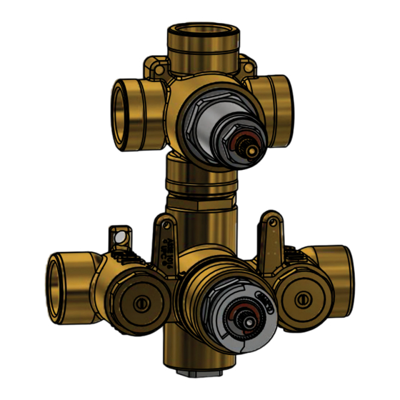
3/4" Thermostatic Valve With 2 or 3 Output Diverter
TVH.4301F
3 OUTPUT
Ver. 2.54
www.isenbergfaucets.com
Installation Manual
BEFORE YOU BEGIN
•
You must observe all local plumbing laws and codes.
•
Do not install this valve if it does not meet local plumbing codes.
•
Shut off the main water supply.
TVH.4420F
2 OUTPUT
Advertisement
Chapters
Table of Contents

Related Manuals for Isenberg TVH.4420F


Summary of Contents for Isenberg TVH.4420F
- Page 1 Installation Manual 3/4” Thermostatic Valve With 2 or 3 Output Diverter TVH.4301F TVH.4420F 3 OUTPUT 2 OUTPUT BEFORE YOU BEGIN • You must observe all local plumbing laws and codes. • Do not install this valve if it does not meet local plumbing codes. • Shut off the main water supply. Ver. 2.54 www.isenbergfaucets.com...
-
Page 2: Table Of Contents
TABLE OF CONTENTS • Operating Specifications . . . . . . . 1 • Valve Installation And Tolerance • Cut-Out Dimensions . . . . . . . • Rough In Specification . . . . . . • Connecting The Supply & Output Lines . . . . . ... -
Page 3: Operating Specifications
This product is to be used with a water pressure range of 15 PSI to 80 PSI ONLY a temperature range of 40˚F - 120˚F ONLY! If water pressure is greater than 80 PSI install a pressure reducing valve (PRV) This valve meets or exceeds ANSI A112.18.1 and ASSE 1016 This valve is certified by IAPMO CUT OUT DIMENSIONS Isenbergʼs TVH Series valves comes with a black pre-attached mud-guard. This mud-guard is not to be removed or discarded. Its purpose is to guide the installation professional on the proper cut-out dimensions of the drywall. Wall Cut Out Dimensions From Center Point of Valve: X = 165mm / 6.49” Y = 113mm / 4.44” www.isenbergfaucets.com... -
Page 4: Rough In Specification
ROUGH IN SPECIFICATION Maximum = 87.5mm [3,44"] Minimum = 70.5mm [2,77"] The distance between back of the valve to the nished tile surface should be between 2.77” and 3.44” inches. Finished tile should fall between Min & Max. If valve is installed too deep into the wall, extensions are available. -
Page 5: Connecting The Supply & Output Lines
CONNECTING THE SUPPLY & OUTPUT LINES Fix Valve on wooden plank Level Valve Attach Hot/Cold Lines www.isenbergfaucets.com... - Page 6 CONNECTING THE SUPPLY & OUTPUT LINES TWO OUTPUT CONFIGURATION VALVE: TVH.4420F Connect the two output supply lines as seen on the left. Do not connect any other way. THREE OUTPUT CONFIGURATION VALVE: TVH.4301F Connect the three output supply lines as seen on the left. www.isenbergfaucets.com...
-
Page 7: Finished Tile Position
FINISHED TILE POSITION Install Drywall and Tile. Ensure finished tile surface is between the min and max marks on the mud guards. www.isenbergfaucets.com... -
Page 8: Using The Supply Stops
USING THE SUPPLY STOPS Turn Clock-wise 5 times to stop water flow. [ Three output valve version shower here ] FLUSHING THE VALVE In order to clear dirt in the lines - you must flush the valve before the wall is closed and water is turned on for the first time. 1) Remove the 2 supply stops by turning with a spanner 2) Remove thermostatic cartridge by turning with a spanner 3) Turn on water supply and let water flow removing any dirt in the lines. www.isenbergfaucets.com... - Page 9 INSTALLING THE TRIM - TRIM PLATE SIZE AND SHAPE MAY VARY - ILLUSTRATION ONLY Remove mud guards Install 42mm ring The 42mm ring must be flush. Otherwise the handle A hard push may be required will not fit properly www.isenbergfaucets.com...
- Page 10 INSTALLING THE TRIM - TRIM PLATE SIZE AND SHAPE MAY VARY - ILLUSTRATION ONLY Align Trim plate till it is straight Insert trim plate Insert adaptor base and tighten Insert centering knob & screws www.isenbergfaucets.com...
- Page 11 INSTALLING THE TRIM - TRIM PLATE SIZE AND SHAPE MAY VARY - ILLUSTRATION ONLY Insert diverter handle. Tighten hex screw & insert Remove anti-scald temperature ring cover button. Make sure the diverter is set to the “OFF” marking before your begin Caliberate cartridge before inserting temperature Correctly re-insert anti-scald temperature ring in the right position. To decrease maximum temperature, remove handle and rotate the anti- handle. Red marks must align. scald ring clockwise. To increase maximum temperature rotate the anti - scald ring counter-clockwise. www.isenbergfaucets.com...
- Page 12 INSTALLING THE TRIM - TRIM PLATE SIZE AND SHAPE MAY VARY - ILLUSTRATION ONLY This photo shows a completely installed trim Insert temperature handle. Tighten hex screw & insert cover button The button on the temperature handle is an anti scald feature. In order to rotate the handle further to “HOT” the button must be pressed www.isenbergfaucets.com...
-
Page 13: Replacing The Thermostatic Cartridge
REPLACING THE THERMOSTATIC CARTRIDGE 1. Remove Anti-Scald Ring 2. The temperature cartridge can be removed easily in one operation by using a spanner. 1. Remove Threaded Rod using a spanner 2. Remove diverter flange 3. Remove cartridge by turning with a span- ner and pulling out with a pair of pliers. REPLACING THE DIVERTER CARTRIDGE www.isenbergfaucets.com... - Page 14 REPLACING THE SUPPLY STOPS In order to remove the supply stops do not twist the Use a spanner to twist in the shown position and screw in the middle of the supply stop remove supply stop www.isenbergfaucets.com...
- Page 15 INSTALLING EXTENSIONS TO THE VALVE - OPTIONAL - ACTUAL VALVE MAY VARY Install diverter extension kit - 3 Pieces as shown Remove anti scald temperature ring above Install temperature extension piece as shown above. Tighten Screw www.isenbergfaucets.com...
- Page 16 USE THE FOLLOWING INSTALLATION MANUAL FOR THE TVH.4420 VALVE...
- Page 17 Installation Manual - TVH.4420 3/4” Thermostatic Valve With 2-Output Diverter Use With Trims Ending in *4420 / *4421 / *4422 BEFORE YOU BEGIN • You must observe all local plumbing laws and codes. • Do not install this valve if it does not meet local plumbing codes. • Shut off the main water supply. Ver. 2.54 www.isenbergfaucets.com...
- Page 18 TABLE OF CONTENTS • Operating Specifications . . . . . . . 1 • Valve Installation And Tolerance • Cut-Out Dimensions . . . . . . . • Rough In Specification . . . . . . • Connecting The Supply & Output Lines . . . . . ...
-
Page 19: Operating Specifications
ONLY! If water pressure is greater than 80 PSI install a pressure reducing valve (PRV) This valve meets or exceeds ANSI A112.18.1 and ASSE 1016 This valve is certified by IAPMO CUT OUT DIMENSIONS Isenbergʼs TVH Series valves comes with a black pre-attached mud-guard. This mud-guard is not to be removed or discarded. Its purpose is to guide the installation professional on the proper cut-out dimensions of the drywall. Wall Cut Out Dimensions From Center Point of Valve: TVH.4420 X = 165mm / 6.49” Y = 113mm / 4.44” www.isenbergfaucets.com... -
Page 20: Rough In Specification
ROUGH IN SPECIFICATION Maximum = 87.5mm [3,44"] Minimum = 70.5mm [2,77"] The distance between back of the valve to the nished tile surface should be between 2.77” and 3.44” inches. Finished tile should fall between Min & Max. If valve is installed too deep into the wall, extensions are available. -
Page 21: Connecting The Supply & Output Lines
CONNECTING THE SUPPLY & OUTPUT LINES Fix Valve on wooden plank Level Valve Attach Hot/Cold Lines Attach Output Lines www.isenbergfaucets.com... -
Page 22: Trim Markings / Water Output
FINISHED TILE POSITION Install Drywall and Tile. Ensure finished tile surface is between the min and max marks on the mud guards. TRIM MARKINGS / WATER OUTPUT The below diagram shows the markings on the trim plate and the outputs on the valve. This will help the installation professional to connect the appropriate accessories to the valve output ports www.isenbergfaucets.com... -
Page 23: Using The Supply Stops
USING THE SUPPLY STOPS Turn Clock-wise 7 times to stop water flow. FLUSHING THE VALVE In order to clear dirt in the lines - you must flush the valve before the wall is closed and water is turned on for the first time. 1) Remove the 2 supply stops by turning with a spanner 2) Remove thermostatic cartridge by turning with a spanner 3) Turn on water supply and let water flow removing any dirt in the lines. www.isenbergfaucets.com... - Page 24 INSTALLING THE TRIM - TRIM PLATE SIZE AND SHAPE MAY VARY - ILLUSTRATION ONLY Remove mud guards Install 42mm ring The 42mm ring must be flush. Otherwise the handle A hard push may be required will not fit properly www.isenbergfaucets.com...
- Page 25 INSTALLING THE TRIM - TRIM PLATE SIZE AND SHAPE MAY VARY - ILLUSTRATION ONLY Align Trim plate till it is straight Insert trim plate Insert adaptor base and tighten Insert centering knob & screws www.isenbergfaucets.com...
- Page 26 INSTALLING THE TRIM - TRIM PLATE SIZE AND SHAPE MAY VARY - ILLUSTRATION ONLY Insert diverter handle. Tighten hex screw & insert Remove anti-scald temperature ring cover button. Make sure the diverter is set to the “OFF” marking before your begin Caliberate cartridge before inserting temperature Correctly re-insert anti-scald temperature ring in the handle. Red marks must align. right position www.isenbergfaucets.com...
- Page 27 INSTALLING THE TRIM - TRIM PLATE SIZE AND SHAPE MAY VARY - ILLUSTRATION ONLY This photo shows a completely installed trim Insert temperature handle. Tighten hex screw & insert cover button The button on the temperature handle is an anti scald feature. In order to rotate the handle further to “HOT” the button must be pressed www.isenbergfaucets.com...
-
Page 28: Replacing The Thermostatic Cartridge
REPLACING THE THERMOSTATIC CARTRIDGE 1. Remove Anti-Scald Ring 2. The temperature cartridge can be removed easily in one operation by using a spanner. 1. Remove Threaded Rod using a spanner 2. Remove diverter flange 3. Remove cartridge by turning with a span- ner and pulling out with a pair of pliers. REPLACING THE DIVERTER CARTRIDGE www.isenbergfaucets.com... - Page 29 REPLACING THE SUPPLY STOPS In order to remove the supply stops do not twist the Use a spanner to twist in the shown position and screw in the middle of the supply stop remove supply stop www.isenbergfaucets.com...
- Page 30 INSTALLING EXTENSIONS TO THE VALVE - OPTIONAL Install diverter extension kit - 3 Pieces as shown Remove anti scald temperature ring above Install temperature extension piece as shown above. Tighten Screw www.isenbergfaucets.com...
- Page 31 CARTRIDGE CLEANING & MAINTENANCE CARTRIDGE CLEANING & MAINTENANCE Thermostatic Cartridge: Clean Filters Check For Dirt Inspect O-rings Diverter Cartridge: Inspect Rubber Seal Check For Dirt Check For Dirt www.isenbergfaucets.com...
Need help?
Do you have a question about the TVH.4420F and is the answer not in the manual?
Questions and answers