Table of Contents
Advertisement
CAUTION: To Reduce The Risk Of Injury, User Must Read
And Understand Operator's Manual. Save These Instructions
For Future Reference.
For questions / comments, technical assistance or repair
parts - Please call toll free at: 1-877-684-8912 (Monday -
Friday 8am - 6pm EST.)
10" Sliding Tile Saw
709-3912
OPERATOR'S MANUAL
Page 1
Advertisement
Table of Contents

Related Manuals for MasterForce 709-3912


Summary of Contents for MasterForce 709-3912
- Page 1 10" Sliding Tile Saw 709-3912 OPERATOR’S MANUAL CAUTION: To Reduce The Risk Of Injury, User Must Read And Understand Operator’s Manual. Save These Instructions For Future Reference. For questions / comments, technical assistance or repair parts - Please call toll free at: 1-877-684-8912 (Monday - Friday 8am - 6pm EST.)
-
Page 2: Table Of Contents
TABLE OF CONTENTS Safety Symbols ................................Page 2 Safety Instructions ............................... Page 3 Overview ..................................Page 8 Speci cations ................................Page 9 Contents ..................................Page 10 Assembly ................................... Page 11 Operation ................................... Page 22 Maintenance ................................Page 28 Troubleshooting ................................. Page 30 Replacement parts list ............................... -
Page 3: Safety Symbols
SAFETY SYMBOLS Some of these following symbols may be used on this tool. Please study them and learn their meaning. Proper interpretation of these symbols will allow you to operate the tool better and safer. Symbol Name Designation / Explanation Volts Voltage Amperes... -
Page 4: Safety Instructions
SAFETY INSTRUCTIONS The purpose of safety symbols is to attract your attention to possible dangers. The safety symbols and the explanations with them deserve your careful attention and understanding. The symbol warnings do not, by themselves, eliminate any danger. The instructions and warnings they give are no substitutes for proper accident prevention measures. WARNING: Be sure to read and understand all safety instructions in this manual, including all safety alert symbols such as “DANGER,”... - Page 5 SAFETY INSTRUCTIONS Please read and understand this entire manual before Make sure switch is in the off position before plugging in. attempting to assemble, operate, or install the tile saw. • DIRECTION OF FEED. Feed work into a tile saw blade against the direction of rotation of the tile saw blade only.
- Page 6 SAFETY INSTRUCTIONS manufacturer. WARNING: The tile saw is loud and the sound can • Use only diamond tile saw blades for which the maximum cause hearing damage. ALWAYS wear ear protection to possible speed is not less than the maximum spindle help prevent hearing damage and loss.
- Page 7 SAFETY INSTRUCTIONS GROUND INSTRUCTION Circuit and Adapter Information FIG. 2 In order to prevent potential electrical shock and injury, the following electrical safety precautions and symbols should be followed at all times! Metal Screw WARNING: Cover Of In case of a malfunction or breakdown, Grounded grounding provides a path of least resistance for electric Outlet Box...
- Page 8 SAFETY INSTRUCTIONS Be sure extension cords are properly wired and in good GLOSSARY OF TERMS condition. Always replace a damaged extension cord The safe use of this tile saw requires an understanding of or have it repaired by a quali ed technician before using it. the information on the tile saw from this operator’s manual Protect extension cords from sharp objects, excessive heat, as well as a knowledge of the project you are attempting.
-
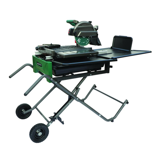
Page 9: Overview
OVERVIEW Blade lock knob Table Rear extension tray Toggle table stop Stand handle Water pump Pump power cord ON/OFF Switch Miter gauge Water tray Pump outlet Power cord Release lever Drain plug Stand Roller wheel Depth lock knob Pump bracket Saw blade Handle Tool storage... -
Page 10: Speci Cations
SPECIFICATIONS 120 V~ 60 Hz 15A Motor No load speed 4500 RPM Diamond tile saw blade 10 in. x 5/8 in. (arbor) Maximum depth of cut 3-3/4 in. Rip capacity (tile size) 24 in. Diagonal Capacity (tile size) 18 in. Bevel cut range 0°, 22.5°, 45°... -
Page 11: Contents
CONTENTS The following items are included with your 10" Sliding Tile Saw: PART DESCRIPTION QUANTITY PART DESCRIPTION QUANTITY Motor Head Assembly 8mm Hex Key Water Tray Frame Assembly Upper Stand Assembly Flat Washer 10 Stand Leg A Hex cap screw M10 x 52 Stand Leg B Table Roller Stand Leg A... -
Page 12: Assembly
ASSEMBLY UNPACKING • Carefully lift the tile saw from the carton and place on a level work surface. WARNING: Do not use this tile saw if any parts on the Loose Parts List are already assembled to your tile saw when you unpack it. - Page 13 ASSEMBLY • Attach the roller stand leg A (U) and roller stand leg B (V) FIG. 3B with horizontal support A (AA) using curved washers (CC) and hex bolts M8 x 50 (DD). • Attach roller stand leg A (U) and roller stand leg B FIG.
- Page 14 ASSEMBLY • Attach the stand leg A (S) and stand leg B (T) with two FIG. 3E horizontal supports B (BB) using curved washers (CC) and hex bolts M8 x 50 (DD). • Attach stand A and stand B assembly to the roller stand FIG.
- Page 15 ASSEMBLY • Grasp the stand handles (EE) and tilt stand and frame FIG. 3H assembly back onto roller wheels (FF) until the stand is balanced on the wheels and stand support assembly. • Step on the release lever (JJ) and pull the stand handles FIG.
- Page 16 ASSEMBLY INSTALLING MOTOR HEAD TO FRAME FIG. 4A AND STAND ASSEMBLY (Fig. 4A-4C) • Align holes in motor head assembly (A) with holes on side of metal frame. Insert hex cap screws M10 x 52 (D) through at washers 10 (C) and into motor head assembly. Secure with 8mm hex key (supplied).
- Page 17 ASSEMBLY INSTALLING THE TABLE (Fig. 5) FIG. 5 • From right side of table (E), pull the table lock lever (MM) out, rotate table stop (NN) to unlock position. Grasp table (E) rmly and set rollers on rails of frame. Holding table (E) parallel with frame, push table toward back of tile saw.
- Page 18 ASSEMBLY • Standing at back of tile saw, insert rear extension tray (J) FIG. 7B into grooves in water tray holder on the water tray frame. • Rotate ap (QQ) on rear extension tray to vertical position. FIG. 7C • Align engraved on side extension tray A (H) with rail FIG.
- Page 19 ASSEMBLY • Place the hooks on side extension tray B (I) into the FIG. 7E corresponding holes on side extension tray A (H). Lower side extension tray B to a horizontal position and place the hook on other end of the side extension tray B (I) into the hole on the rear extension tray (J).
- Page 20 ASSEMBLY INSTALLING THE MITER GUIDE (Fig. 9) FIG. 9 The miter guide can be used from both the left and right side of the tile saw blade. • Place slot on underside of the miter guide (G) on table fence. Lock the miter guide (G) securely to table by turning lock knob (VV) clockwise.
- Page 21 ASSEMBLY CAUTION: The tile saw is equipped with two water nozzles (dd) to wet the tile saw blade during operation. Make sure holes in nozzles face the tile saw blade and that tile saw blade is positioned between the two nozzles. •...
- Page 22 ASSEMBLY • Align the hole (gg) on each end of the side splash guard FIG. 11C (N) to the screw (hh) on each side of the blade guard and press the holes (gg) on the splash guard through the screws (hh). CAUTION: It is not necessary to loosen or remove the screws (F) on the blade guard to install the side splash...
-
Page 23: Operation
OPERATION WARNING: DO NOT allow familiarity with the tile saw to make you careless. Always wear safety protection. Failure to do so could result in objects being thrown into your eyes, resulting in possible serious injury. DO NOT use any attachments or accessories not recommended by the manufacturer of this tile saw. - Page 24 OPERATION DEPTH ADJUSTMENT (Fig. 14) FIG. 14 • Depth knob: The depth knob (ll) can be used to lock the motor head at a particular cutting depth; tighten it to lock the motor head in place, loosen it to allow adjustment. •...
- Page 25 OPERATION FILLING THE WATER TRAY (FIG. 16) FIG. 17 • Place the drain plug (PP) into the hole on the bottom of the water tray (L). • Fill the water tray (L) with clean water up to the maximum ll line before every use. CAUTION: Water level must be kept above minimum ll line (oo) and below maximum ll line (pp) at all times during...
- Page 26 OPERATION • With the tile saw running, make sure the pump is supplying FIG. 17C enough water to the tile saw blade. • Let the tile saw blade build up to full speed before cutting. • Use two hands and hold workpiece securely against table and fence at all times.
- Page 27 OPERATION CLOSING OPENING STAND FIG. 18A (FIG. 18A-18E) • Unplug the tile saw and water pump. • Remove water rear and side extension trays and store them inside the water tray. Remove any work pieces from the tile saw. CAUTION: When storing, place the rear extension tray at the bottom, side extension tray B on the middle and rear extension tray A on the top.
- Page 28 OPERATION OPENING STAND (FIG. 18D-18E) FIG. 18D • Step on the release lever (JJ) and pull the handles (EE) toward you at the same time. • Once the stand is released from the release lever, ease the stand toward the oor by pushing the handles toward the oor.
-
Page 29: Maintenance
MAINTENANCE WARNING: When servicing, use only identical Masterforce replacement parts. Use of any other parts may create a hazard or cause product damage. ALWAYS wear eye protection with side shields marked to comply with ANSI Z87.I during product operation. If operation is dusty, also wear a dust mask. DO NOT at any time let brake uids, gasoline, petroleum- based products, penetrating oils, etc., come in contact with plastic parts. - Page 30 MAINTENANCE BRUSH REPLACEMENT (FIG. 19) FIG. 19 The tile saw has externally accessible brush assemblies that should be periodically checked for wear. Proceed as follows when replacement is required: • Unplug the tile saw. • Remove brush cap (zz) with a at head screwdriver (not included).
-
Page 31: Troubleshooting
TROUBLESHOOTING PROBLEM PROBLEM CAUSE CORRECTIVE ACTION Motor is too hot. • The machine is overheated. • Turn off machine and let it cool down to room temperature. • Ventilation is obstructed. • Check and clean ventilation. Motor stops turning. • Plugs have not been fully connected. •... -
Page 32: Replacement Parts List
REPLACEMENT PARTS LIST For questions / comments, technical assistance or repair parts - Please call toll free at: 1-877-684-8912 (Monday - Friday 8am - 6pm EST.) PART DESCRIPTION PART# PART DESCRIPTION PART# Side Splash Guard 70939120001 Table Stop 70939120010 Rear Splash Guard 70939120002 Arbor Wrench 70939120011... -
Page 33: Warranty
This MASTERFORCE ® brand power tool carries our famous No Hassle 3-Year Limited Warranty to the original purchaser. If, during normal use, this MASTERFORCE ® power tool breaks or fails due to a defect in material or workmanship within three (3) years...
Need help?
Do you have a question about the 709-3912 and is the answer not in the manual?
Questions and answers
I'm looking for a replacement steel roller wheel for the sliding table.
Need roller bearings for the sliding table