Table of Contents
Advertisement
Quick Links
http://www.dropsa.com
Via Benedetto Croce, 1
Vimodrone, MILANO (IT)
t. +39 02 250791
VIP5 Pro Controller
Control system for small and medium size
Lubrication Systems
Software Version 3.0
User Operating and Maintenance
Manual
Original text translation
CONTENT
1.
2.
3.
4.
FIXING AND INSTALLATION DETAILS
5.
6.
7.
8.
9.
Manual compiled in accordance with Directive
06/42 CE
Dropsa products can be purchased from Dropsa branches and authorized distributors, visit
www.dropsa.com/contact or contact us sales@dropsa.com
C2162IE - WK 43/19
Advertisement
Table of Contents

Related Manuals for DROPSA VIP5 Pro


Summary of Contents for DROPSA VIP5 Pro
-
Page 1: Table Of Contents
Manual compiled in accordance with Directive C2162IE – WK 43/19 Via Benedetto Croce, 1 06/42 CE Vimodrone, MILANO (IT) Dropsa products can be purchased from Dropsa branches and authorized distributors, visit t. +39 02 250791 www.dropsa.com/contact or contact us sales@dropsa.com... -
Page 2: Introduction
1. INTRODUCTION Thank you for purchasing the Dropsa VIP5 Pro controller – The control device for Lubrication Systems The Controller subject of this operating and maintenance manual is an evolution of the Vip5 family of advanced lubrication control system. It maintains all its basic features and has additional functions and features such as the ability to directly switch on/off three-phase pump and other devices. -
Page 3: Product Features
LUBRICATION Phase (Lube –> Wait stages) -> This is when lubricant is provided (as above) STANDBY Phase -> The system is inactive awaiting for the next LUBRICATION PHASE Additionally, the VIP5 Pro Control system can also be used as a simple monitoring device in the “FLOW” operating Mode described later in this manual. - Page 4 The user can specify the number of lubrication cycles up to a maximum of 250. If Prelube is set to zero, the VIP5 Pro controller will not perform any pre-lubrication; in this case if the START parameter setting is "Resume", when the system is turned on it will revert to its pre-power down, or it will start from a lubrication cycle if the setting of the start is "Lube".
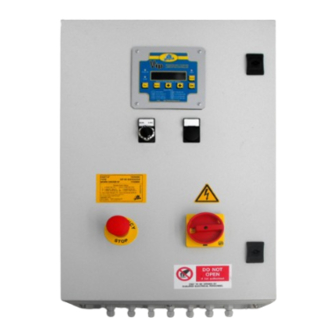
- Page 5 INLETS/OUTLETS 4.1 ELECTRICAL CONNECTIONS Inside the panel there are 6 connection terminal strips available (see image). XM0 power supply connection of the panel and to the three-phase command of the outlet pump XM1 digital inputs connection XM3 analogue inputs connection XM4 exchange signals connection XM5 digital outlet connection (pneumatic or electromagnetic valve) The connection of the cables in the terminal strip depends on the type of configuration used (SEP, DUAL, TIME, DUAL...
- Page 6 6/27...
- Page 7 Table 1 NPN signals connection Insert the jumper as indicated in the image below Max Level Min Level Pulse Input/Suspend Cycle Sensor PS 1 PS 2 7/27...
- Page 8 Table 2 PNP signals connection Insert the jumper as indicated in the image below Max Level Min Level Pulse Input/Suspend Cycle Sensor PS 1 PS 2 8/27...
- Page 9 Table 3 There are five connection terminal strips inside the panel called XM0, XM1, XM3, XM4 and XM5 (see image below). The panel power supply voltage and the three-phase output command toward the pump should be connected to the XM0 terminal strip.
-
Page 10: Inputs/Outputs
5. INPUTS/OUTPUTS 5.1 ELECTRICAL CONNECTIONS As indicated on the electrical diagram of equipment (Part #1327290), it is suggested to use 2.5 mm2 section cable. The maximum thermal protection mounted on equipment can be 4 A. NOTA: Nel collegamento dei dispositivi “da e verso il campo”, utilizzare le canalizzazioni predisposte internamente al quadro. - Page 11 For further details also check the completed electrical diagram enclosure with your specific equipment. Fig. 4 NOTE: To connect micro-switches or clean contacts inputs, equipped by creating a terminals for the positive power supply (+) and the relative input P (IN +), you must make a link between (+) and (IN+) after that connect the 2 wires of micro-switch at (-) or (IN-) 11/27...
- Page 12 Location Signal level Function Note Block 24 Vdc inputs (Vio+) input P IN + Max level 0 Vdc inputs (Vio-) input N IN - 24 Vdc inputs (Vio+) Input P IN + Min level 0 Vdc inputs (Vio-) Input N IN - 24 Vdc inputs (Vio+) Input P...
- Page 13 4:20 mA reference Location Signal level Function Note Block SPST, 3 A 250Vac Command "Alarm" on resistive load Vip5 Pro panel SPST, 3 A 250Vac Command cleaning resistive load nozzles SPST, 3 A 250Vac Load command resistive load SPST, 3 A 250Vac...
- Page 14 Fig. 5 By inserting the Jumper into the bridging pins, the battery function is activated and this allows the VIP5 Pro to operate with the Date/time and status save function when the power is removed. Note: Every time the battery jumper is removed and reinserted causes the DATE/TIME function to be set to zero.
- Page 15 The external protection cable with a gauge equal to that of the power supply phase cable must be connected. It is therefore compulsory to connect the bolt or the ground terminal strip to the mains power supply grounding system. Check the efficiency of the customer’s pre-existing grounding system preventively. Request the certification of the customer’s pre-existing grounding system preventively.
-
Page 16: Operator Interface Front Panel
Next Parameter or Setting MODE (SET): ESC: Increase displayed value Change Value for selected Exit from setup menu without saving parameter changes VIP5 Pro Condition PUMP ON LED CYCLE INPUT LED ALARM LED Alarm Standby Phase Lubrication Phase/Cycle Setup 16/27... -
Page 17: Operating Mode
7. OPERATING MODE VIP5 Pro has three different operating modes which are determined during the setup stage described previously. These are: CYCLE, PULSE and FLOW. 7.1 CYCLE Mode In Cycle mode a cycle sensor determines the completion of the LUBRICATION PHASE. If using timer setting, the Lubrication Cycle will complete when the timer expire. - Page 18 7.3 FLOW Mode Using this mode allows the VIP5 Pro to be used as a simple flow monitoring and display device. Pump on ALLARM Flow control Flow Out of Range Lubrificazione The display shows the current Flow rate being detected in the system.
-
Page 19: Cycle Monitoring
1) DUAL – DUAL LINE Dual Line cycles generally use two pressure switches connected to P1 and P2. The VIP5 Pro starts the pump and must see that P1 switch is closed within the timeout Power time. After this, the Lubrication lines are... - Page 20 3) PS – PRESSURE SWITCH Pressure switch monitoring is typically used in injector system. POWER MOTOR The VIP5 Pro will monitor input P1 to verify PUMP ALARM that it is an OPEN contact at the start of the cycle. The pump is activated and the pressure switch must CLOSE within a timeout period otherwise a cycle alarm is generated.
-
Page 21: Setup Programming
9. SETUP PROGRAMMING The following section explains how to navigate the VIP5 Pro setup menus and contains detailed explanation of each parameter and possible values. 9.1 Navigating around the setup menu. The navigation map below shows how to navigate around the setup menu. - Page 22 9.2 PARAMETERS AND VALUES The following table shows the parameters and possible values of . The first two parameters (MODE and VIP5 Pro TYPE) determine what parameters are available in the menu and they are the first that must be set. PARAMETER...
- Page 23 Never stop the lubrication cycle On None All alarm conditions On All STOP On All All but min Level stops the Vip5 pro All But Min Level Only minimum level alarm stops the VIP5 All But Max Level All but Maximum Level Minlev Only MIN.
-
Page 24: Problems And Solutions
An unknown Internal error has occurred. ALARM 15 UNCODED FAIL Try resetting the unit. If the error re-occurs, the unit must be returned to Dropsa for inspection. EXTERNAL ALARM 16 Overpressure alarm and safety signal in air-oil systems. -
Page 25: Technical Specifications
10.3 REMOTE CODED ALARM FUNCTION The VIP5 controller has the ability to use a remote pulsed coded alarm contact. Every time the VIP5 control enters an alarm condition, the remote alarm relay contact is activated. Most alarm contacts are simply a NC or NO contact that gives a remote system indication that the local controller is in a fault condition. -
Page 26: Mounting And Installation Details
Per lo smaltimento, fare riferimento ai regolamenti locali. 12.2 INSTALLAZIONE Il VIP5 Pro deve essere garantito fisicamente a una posizione di montaggio e cablato a tutte le componenti del Sistema di Lubrificazione. It is recommended to: •... -
Page 27: Maintenance Procedures
13. MAINTENANCE PROCEDURES VIP5 Pro has been designed not to require any regular maintenance. We recommend to occasionally cleaning the unit with a damp cloth, not using solvents The battery life is approximately 10 years. In the event that the battery needs to be replaced you should note that there are two possible battery types.
Need help?
Do you have a question about the VIP5 Pro and is the answer not in the manual?
Questions and answers