Table of Contents
Advertisement
Quick Links
http://www.dropsa.com
Via Benedetto Croce, 1
Vimodrone, MILANO (IT)
t. +39 02 250791
FACT
Controller
S/W Ver. 1.50
User and Maintenance Manual
Original text translation
Warranty Information
TABLE OF CONTENTS
1.
2.
3.
4.
5.
6.
7.
UNPACKING AND INSTALLALLING THE EQUIPMENT
8.
9.
10.
11.
12.
13.
14.
15.
16.
WARRANTY INFOMATION
17.
DECLARATION OF COMPLIANCE
18.
DISTRIBUTORS
The manual has been prepared in compliance with Directive
CE 06/42
Dropsa products can be purchased from Dropsa branches and authorized distributors, visit
www.dropsa.com/contact
or contact us
sales@dropsa.com
C2209IE WK 30/16
Advertisement
Table of Contents

Related Manuals for DROPSA FACT


Summary of Contents for DROPSA FACT
-
Page 1: Table Of Contents
The manual has been prepared in compliance with Directive Via Benedetto Croce, 1 CE 06/42 C2209IE WK 30/16 Vimodrone, MILANO (IT) t. +39 02 250791 Dropsa products can be purchased from Dropsa branches and authorized distributors, visit www.dropsa.com/contact or contact us sales@dropsa.com... -
Page 2: Introduction
2.2 ACCESSORIES You can expand the number of flow monitored by the FACT by connecting to FACT EXPANDER that can manages an additional 16 flow meters. Up to seven FACT REMOTE EXPADNER MODULES can be connected to a single FACT enabling the control of up to 128 Flow switches. -
Page 3: Machine Identification
FACT is used to manage flowmaster flow measurment and regulation devices (see DROPSA "Flowmaster" product) used primarily in oil recirculating systems. The FACT and Flowmaster products can be used in any applications that requires acurate point-for-point montiroing and control of lubricant flow in oil-recirculation systems 3. -
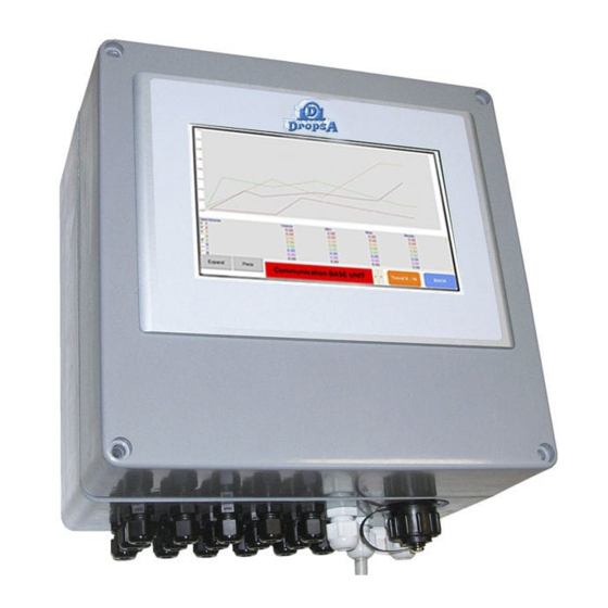
Page 4: Equipment
5. EQUIPMENT FACT has a touch screen LCD display that allows users to interface and set the operations of controller. A tree structure Sub- menu allows access to all the parameters. You will see the pages linked from the main display menu listed on in par.9. - Page 5 More detailed information related to this product are described in the product manual that can be downloaded from our website http://www.dropsa.com. Fig. 3 7. UNPACKING AND INSTALLALLING UNPACKING Once a suitable location has been found to install the unit remove the equipment from the packaging. No particular disposal procedures are necessary;...
- Page 6 7.3 ELECTRIC CONNECTIONS 7.3.1 FACT CPU BOARD ATTENTION: Before opening the equipment disconnects power and wait 5 minutes. Dip-switches Touch screen connection Terminal Strip C Terminal Strip B RS485 OUT Flowmaster Flowmaster terminal 1-8 terminal 9-16 Touch screen Terminal supply X1 Power Supply Fig.
- Page 7 The dip-switches is divided into 2 parts: from 1 to 3 sets the number of FACT EXPANDER, and from 4 to 6 sets if the...
-
Page 8: Operating Instructions
To set the FACT-EXPANDER number, that must be included from 1 to 7 and in sequential order, use the following table. N° FACT EXPANDER DIP-SWITCH 1 DIP-SWITCH 2 DIP-SWITCH 3 To set the signals from Flowmaster you must set the 3 dip-switches from 4 to 6 ON to configure input signals as signals "P", or set OFF to configure the input signals as signals "N". - Page 9 MONITOR When turned on, the display shows the Flowmaster status. On the screen displays the nominal value of flow rate setted and value measured for each Flowmaster installed. A light indicates that flow behaviour in relation to min and max thresholds, high and low settable (see par.8.3) precisely: •...
- Page 10 From the main page by going to the menu screen appears as in the image below. From this dynamic page (the keys appear depending on the type of access that has) can access the various configurations of the FACT. For the password contact Dropsa offices.
- Page 11 8.3 SETTINGS This page shows types of Flowmaster installed. You can set the nominal values of minimum, low, high and maximum value of each flow. Once set the nominal flow rate (trough a touch on the box), you can choose whether to insert other values automatically, using the auto set button and selecting flow meter number, or entering values by manually respecting following steps: ...
- Page 12 Program version greater than 4 See chap. 8.7 8.5 HISTORIAN This page shows all alarm in the last week, in addition thanks to a USB connector on FACT you can save this data in an USB key.
- Page 13 8.7 INSTALLATION You can set how many fact-expanders are installed \ managed and set the types of Flowmaster installed throughout the system. Set the number of expansions by a touch on the appropriate box and enter the base unit and any installed expansion...
- Page 14 8.8 TREND Trend page shows a graphic of flow measurement. Total period of graphic is 8 hours and it’s possible to set the scale range of measure value for each flow channel. It’s possible to hide or display a measure channel. The measure graphic is active and memorize only when the page is showed, when the page is closed all data are cleared.
-
Page 15: Troubleshooting
Check that jumpers on all devices is set correctly 10. MAINTENANCE PROCEDURE FACT ordinary maintenance: - Clean FACT-2000 box with a damp cloth. Do not use solvents. - Check cable glands are tightened. The electronic system does not require any maintenance. - Page 16 FLOWMASTER COMPLETE MODULE Flow r/min PART NUMBER Sensor type Material cm³ cu. in. 1523730 0,30 1523740 0,61 1523750 1,22 AISI 316 1523870 0,30 1523880 0,61 1523890 1,22 1523732 0,30 1523742 0,61 1523752 1,22 Aluminium 1523872 0,30 1523882 0,61 1523892 1,22 FLOWMASTER SPARE PARTS PART NUMBER DESCRIPTION...
-
Page 17: Dimensions
FACT controllers are packed and dispatched in cardboard containers. During transportation and storage always maintain the unit the right way up as indicated on the box. On receipt check that the packaging has not been damaged and store the FACT in a dry place.
Need help?
Do you have a question about the FACT and is the answer not in the manual?
Questions and answers