Table of Contents
Advertisement
Quick Links
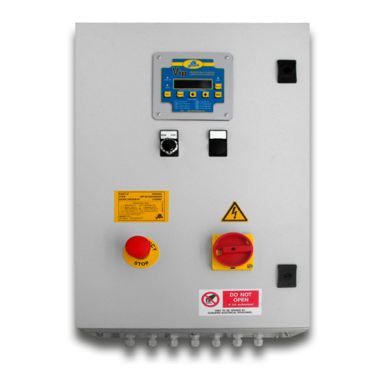
VIP5 Pro Controller
Control system for small and medium size
Lubrication Systems
Software Version 3.0
Version in compliance with Directive CE 94/9 (ATEX)
User Operating and Maintenance
Manual
Original text translation
TABLE OF CONTENTS
1.
2.
MARKING PRODUCT
3.
4.
5.
6.
7.
8.
9.
10.
11.
12.
PROBLEMS AND SOLUTIONS
13.
TECHNICAL SPECIFICATIONS
14.
15.
ORDERING INFORMATION
16.
17.
II 2GD Exd IIB+H2 T6 IP65
Manual drawn up in accordance with
EC Directive 06/42
C2163IE WK 41/14
Advertisement
Table of Contents

Related Manuals for DROPSA VIP5 Pro


Summary of Contents for DROPSA VIP5 Pro
-
Page 1: Table Of Contents
VIP5 Pro Controller Control system for small and medium size Lubrication Systems Software Version 3.0 Version in compliance with Directive CE 94/9 (ATEX) User Operating and Maintenance Manual Original text translation TABLE OF CONTENTS INTRODUCTION MARKING PRODUCT TECHNICAL CHARACTERISTICS PRODUCT FEATURES... -
Page 2: Introduction
– controller – The control device for Lubrication Systems The Controller subject of this operating and maintenance manual is an evolution of the Vip5 Pro Atex family of advanced lubrication control system. It maintains all its basic features and has additional functions and features such as the ability to directly switch on/off three-phase pump and other devices. -
Page 3: Technical Characteristics
This is useful for process control and generally used in re-circulating systems. 5.1 CYCLE and PULSE Control System operating Principles. The VIP5 Pro Atex control system is designed to control intermittent or continuous lubrication system with a variety of control inputs. Intermittent operating principle is based on three distinct phases. - Page 4 5.1.3 STANDBY Phase During the Standby the VIP5 Pro Atex switches off the pump and waits for the start of another Lubrication Phase. The duration of the Standby phase can be determined by a countdown timer or a by an external pulse signal that can be used as a counter.
-
Page 5: Inputs/Outputs
6. INPUTS/OUTPUTS 6.1 ELECTRICAL CONNECTIONS Fig. 3 Inside the control panel there are six connecting terminal boards (see image). Terminal Board must be connected to supply voltage of control panel and three phase output control of the pump. Terminal Board must be connected to Input- devices Terminal Board must be connected to Analog- devices Terminal Board must be connected to customer exchange signals Terminal Board must be connected to output –... - Page 6 DUAL TIME DUAL TIME P=PS1 INPUT / C=CYCLE SENSOR Tab.1 5/25...
- Page 7 For NPN Connections Insert the commoning multiple bar as below Connection without Ex Barrier Connection with Ex Barrier Max Level Max Level Min Level Pulse Input/Suspend Cycle Sensor PS 1 PS 2 Tab.2 6/25...
- Page 8 For PNP Connections Insert the commoning multiple bar as below Connection without Ex Barrier Connection with Ex Barrier Max Level Max Level Min Level Pulse Input/Suspend Cycle sensor PS 1 PS 2 Tab.3 7/25...
- Page 9 Location Function Block SUPPLY PANEL PUMP CONTROL Block Signal level Function Note Block IF SENSOR IS NOT EX CERTIFIED, SHOULD MAXIMUM LEVEL DIGITAL INPUT BE CONNECTED TO BARRIER, XD 1/2 INPUT (SIMPLE DEVICE) MINIMUM LEVEL DIGITAL INPUT INPUT PULSE DIGITAL INPUT INPUT/SUSPEND IF SENSOR IS NOT EX CERTIFIED, SHOULD PRESSURE...
- Page 10 All input and output signals refer to a nominal voltage of 24Vdc. The outputs on terminal board M1 refer to voltage indicated as Vio on terminal 6 and 7 of M2. The framework is provided with (Vio) power supply input coinciding with (Vint) internal power supply via bridges on the terminals: M2: M2.5 with M2.7, M2.4 with M2.6 4.
- Page 11 Location Signal level Function Note Block 24 Vdc Inputs (Vio+) Input P IN + Max level 0 Vdc Inputs (Vio-) Input N IN - 24 Vdc Inputs (Vio+) Input P IN + Min level 0 Vdc Inputs (Vio-) Input N IN - 24 Vdc Inputs (Vio+) Input P...
- Page 12 4:20 mA reference Location Signal level Function Note Block SPST, 3 A 250Vac Command "Alarm" on resistive load Vip5 Pro panel SPST, 3 A 250Vac Command cleaning resistive load nozzles SPST, 3 A 250Vac Load command resistive load SPST, 3 A 250Vac...
- Page 13 Fig. 5 By inserting the Jumper into the bridging pins, the battery function is activated and this allows the VIP5 Pro controller to operate with the Date/time and status save function when the power is removed. Note: Every time the battery jumper is removed and reinserted causes the DATE/TIME function to be set to zero.
-
Page 14: Operator Interface Front Panel
Exit from setup menu without saving changes Hardware Reset Button Exit from setup menu saving changes Instant stop button ON - OFF VIP5 Pro Atex Condition PUMP ON LED CYCLE INPUT LED ALARM LED Alarm Standby Phase Lubrication Phase/Cycle Setup... -
Page 15: Operating Mode
8. OPERATING MODE VIP5 has three different operating modes which are determined during the setup stage described previously. These are: CYCLE, PULSE and FLOW. 8.1 CYCLE Mode In Cycle mode a cycle sensor determines the completion of the LUBRICATION PHASE. If using timer setting, the Lubrication Cycle will complete when the timer expire. - Page 16 The Prelube cycle is a pre-lubrication cycle that is triggered when the system is powered on or reset. If the pre-lube cycle value is set to 1 or greater the VIP5 Pro Atex will perform the set number of Lubrication Phases.
-
Page 17: Cycle Monitoring
There are four possible Cycle Monitoring Options, explained below. 1) DL – DUAL LINE Dual Line cycles generally use two pressure switches connected to P1 and P2. The VIP5 Pro controller starts the pump Power and must see that P1 switch is closed within the timeout time. - Page 18 ALARM Once P1 changes state twice, the pump is MINIMUM LEVEL switched off and VIP5 Pro controller PUMP ELETTROVALVE POWER goes to standby or the Lubrication Cycle is POWER repeated for the desired number of times.
-
Page 19: Setup Programming
Per questo tipo di prodotto invece, nato principalmente per la gestione di impianti a linea doppia, è necessario selezionare “extended” per accedere al menù completo di configurazione. Per la lista completa dei parametri avanzati del VIP5 Pro impostabili tramite menù esteso fare riferimento alla tabella del par. 10.3. - Page 20 10.2 PARAMETERS AND VALUES The following table shows the parameters and possible values of VIP5 Pro controller . The first two parameters (MODE and TYPE) determine what parameters are available in the menu and they are the first that must be set.
- Page 21 LCD; hold down OK the contrast decreases, with ESC increases; FLOW TOTALIZER DATA VISUALIZATION: with the VIP5 Pro Atex in standby mode, pressing the OK key will allow you to scroll through the current average flow rate, or the total volume dispense in the last DAY, HOUR or TOTAL since last reset;...
-
Page 22: Fixing And Installation Details
UN-PACKING 11.1 Once the installation point has been identified, you can unpack the VIP5 Pro Atex from its shipping box. Check that the unit has not been subject to any damage during transport. Dispose of the packaging in an appropriate manner, following local waste regulations. - Page 23 12. PROBLEMS AND SOLUTIONS ATTENTION: The VIP5 Pro Atex should only be repaired by qualified Dropsa technicians. 12.1 ALARM CODE TABLE The following is a list of possible alarms generated by the VIP5 Pro Atex with information for troubleshooting purposes. ALARM CODE DESCRIPTION NOTES/CHECKS/SOLUTIONS The Low level sensor has triggered.
-
Page 24: Disposal Procedures
By pressing the button located under the “Setup” label, the user can go and modify the parameter values if it is some incorrect parameter that is causing the alarm. By pressing the button located under “Reset” (or the hard reset button) the VIP5 Pro Atex will restart its programming with the last saved parameters. -
Page 25: Moving And Shipping
N°2 glands • N°4 glands • N°4 plugs M20 15.2 SPARE PARTS AND ACCESSORIES Here is a list of glands and cap codes purchased from Dropsa SpA: Cod.: 75053 glands Cod.: 75066 glands Cod.: 39384 glands Cod.: 75070 plugs M20 16.
Need help?
Do you have a question about the VIP5 Pro and is the answer not in the manual?
Questions and answers