Table of Contents
Advertisement
Quick Links
Advertisement
Table of Contents

Related Manuals for Dreadbox telepathy


Summary of Contents for Dreadbox telepathy
- Page 2 WARRANTY INSTALLATION SIGNAL PATH TELEPATHY OVERVIEW PANEL CONTROLS PATCH POINTS VOICE SECTION MENU SECTION TUNING MODE POLYPHONY / MULTITIMBRALITY FIRMWARE UPDATE...
-
Page 3: Warranty
Always turn off your Dreadbox warrants this product to be free of Eurorack system before defects in materials or construction for one year installing the Telepathy from the date of purchase. module. Telepathy has a Proof of purchase is necessary when the Power consumption of warranty claim is made. - Page 4 PLEASE NOTE: The red stripe should achieve this, send the MIDI OUT to The jack converter is an A type. The Telepathy module always be on the bottom side of the module the MIDI IN of the next Telepathy.
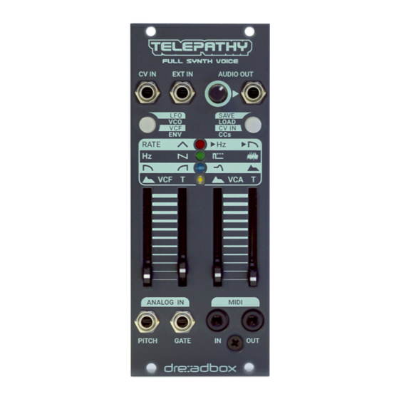
- Page 6 With lots of useful and musical features Telepathy has an intuitive parameter integrated into a compact size (10hp), and navigation matrix, with multicoloured also its skiff friendly design, Telepathy is a LED indication. great addition to a smaller or a larger eurorack system.
-
Page 7: Panel Controls
Telepathy consists of two main sections to navigate its menu. Telepathy uses a simple yet very effective control matrix to navigate through its multiple parameters and affect the sound. It always follows a top down approach. SECTIONS The two buttons on the panel indicate and control the two main sections of the module. -
Page 8: Shift Function
Pressing the button that corresponds to one of the sections you can CV IN: Accepts any external CV signal rated at ±5 Volts. Through cycle through the different Pages (Matrix rows). the CV IN Menu Page, you can assign all the main parameters by setting each independent modulation amount. - Page 9 By pressing the Voice Button we enter the Voice Pages and adjust the parameters of the matrix with the four sliders. Slider 1 Slider 2 Slider 3 Slider 4 The Voice Section consists of four Pages. The LFO, VCO, VCF, ENV. LFO Rate LFO Wave LFO Pitch Amount...
- Page 10 Slider3 LFO PITCH AMT: It adjusts the LFO modulation amount of the VCO pitch. BPM sync: The LFO rate tracks the MIDI clock, independent of the played note. The LFO rate works in divisions of 1, 2, 3, 4, 6, 8, 12, 16, 24, 32. Slider4 LFO CUTOFF AMT: It adjusts the LFO modulation amount of the LP BPM key sync: The LFO rate tracks the MIDI clock and its waveform is...
- Page 11 Slider3 PW: It changes the PW of the square wave. VCF SHIFT PAGE: (Can be accessed by holding the Voice Page Button Slider4 Noise Level: It adjusts the volume of the noise source. while adjusting the sliders value). VCO SHIFT PAGE: (It can be accessed by holding the Voice Page Button Tracking: It adjusts the key tracking amount of the LP Filter Cutoff.
- Page 12 Slider1 PAGE 4 ENVELOPE (WHITE LED) VCF EG SHAPE: It adjusts the Shape of the VCF Envelope. The Envelope follows the classic ADSR sound shaping approach over VCF EG TIME: It adjusts the Time of the VCF Envelope. Slider2 time, but with a twist on the way it gets controlled via a SHAPE, TIME VCA EG SHAPE: It adjusts the Shape of the Envelope applied to the VCA.
- Page 13 EXAMPLE VOICE SECTION Press the Voice Button once, to enter the Pages of the Voice Section (LFO, VCO, VCF, ENV). The red LED light on the first matrix row is on, to indicate that we are now in the first Page, in this case the LFO Page. Move the 1 st slider to affect the rate of the LFO.
-
Page 14: Menu Pages
menu section By pressing the Menu Button we enter the MENU PAGES. The Slider 1 Slider 2 Slider 3 Slider 4 procedure of navigating the parameter is identical to the VOICE SAVE Bank Preset SECTION. We enter the MENU PAGES by pressing the Menu Button Long Press Menu Button to Save the selected Preset. - Page 15 The Banks and Preset Slots start at the bottom with both sliders in the A fast flashing of the LED indicates the Preset Slot number. minimum position and progressively go to increase Banks and Preset When the Bank and Preset Slot position coincide (1,1), (2,2), (3,3), (4,4) Slots by adjusting the position of the sliders.
- Page 16 EXAMPLE ( Schema 7 ) Constant RED to indicate SAVE PAGE Loading a preset located in Bank 1, Preset Slot 4 (1,4) Fast blinking GREEN (PRESET SLOT) Press the Menu Button to enter the LOAD Page indicated by the green Slow blinking BLUE (BANK) LED in row 2 of the matrix and also by a slow flashing on the Menu Button.
- Page 17 (BLUE LED) • Adjust the CV IN amount to modulate the LP Filter Cutoff via slider 1. Telepathy can accept CV signals, through its assignable CV IN input. In this way, external CV sources can be assigned to modulate VCO WAVESHAPE CV Navigate in the Voice Section to the VCO Page (2 nd matrix row, Telepathy’s parameters.
- Page 18 2 to activate the CC OUT. The same applies to Program Pitch LFO Amount CV Amount Noise Level changes. With the use of the 3 rd slider, Telepathy responds to program Cutoff LFO Amount CV Amount changes (PC IN) and with the use of the forth slider it sends program...
-
Page 19: Tuning Mode
Pressing the Voice Button (left) will exit the Tuning Mode. last note your device will output when no change is heard on Telepathy’s oscillator) and press Menu Button once. A flashing on all FINE TUNE 4 LEDs will start and then stop. - Page 20 Hard Master mode. This means that the MASTER to enter the Chain Mode. Telepathy (the unit you set the chain) will transmit all the CCs when 3. Chain Mode is indicated by an alternating flashing of the button LEDs.
-
Page 21: Additional Information
1st module (Master) ADDITIONAL INFORMATION: CC in/CC out, PC in/PC out enabled (send and receive data) 2nd-6th modules (Chained) • When setting up a chain, the MIDI channel, CC and PC settings will Only CC in, PC in enabled (receive data from the Master module but be forced on both Master and Chained units. -
Page 22: Firmware Update
firmware update BOOTLOADER Before powering up the device, press and hold the Menu Button to enter update mode. ALL LEDs are BLINKING. • To upload a firmware update you will need a computer and an application that can handle MIDI SysEX files like Bome SendSX or SysEx Librarian.
Need help?
Do you have a question about the telepathy and is the answer not in the manual?
Questions and answers