
Related Manuals for Dreadbox Dysphonia


Summary of Contents for Dreadbox Dysphonia
-
Page 1: Table Of Contents
CONSTRUCTION & OPERATION Manual 1. Construction 1.1 What's in the box 1.2 Bag parts 1.3 Tools you will use 1.4 Preparation of the bottom board 1.5 Preparation of the power board 1.6 Preparation of the top board 1.7 Connection of the top and bottom boards 1.8 Finalization of the module 2. -
Page 2: Construction
1. Construction BEFORE YOU GET STARTED Before you start the construction of this DIY project, make sure you have basic soldering skills and that you can identify the electronic components. If it is your first time soldering, there are several tutorials on youtube that can help you :) It would be easier and helpful for you to work on a big desk, so as to have plenty of space to work on. -
Page 3: Bag Parts
1.2 Components In the bag we've included all of the hardware parts - 46 x 3,5mm stereo jack - 13 x 100KB plastic rotary pot - 8 x 10KB slider pot - 2 x pushbutton with red LED - 3 x female 20 pin connector headers - 1 x female 10 pin connector header - 1 x male 10pin ribbon connector header - 1 x USB jack... -
Page 4: Preparation Of The Bottom Board
1.4 Preparation of the bottom board For this step you will need: - The bottom board - A Soldering iron - 0.7mm solder wire - A Cutter - The 10pin ribbon male header Solder the ribbon header to the bottom side of the board as shown in the pictures... -
Page 5: Preparation Of The Power Board
Then, cut the excess wires from the pre-assembled trimmers and remove the extra PCB from the top and bottom side of the board. 1.5 Preparation of the power board For this step you will need: - The 0.7 solder wire + a soldering iron - The USB jack - The 10pin female header Solder the USB jack and the header, as shown in the pictures. -
Page 6: Preparation Of The Top Board
1.6 Preparation of the top board Start by removing the excess PCB from the board Locate and place the 3.5mm jacks on the board Then solder these by using the 1.5mm wire... - Page 7 Next, locate the two push buttons. WARNING! They have a polarity that needs to be respected! If not placed correctly they will be damaged and removing them is a challenging task! Check their bottom side. The "+" sign should match the square pad on the PCB.
- Page 8 The next step is to solder the slider potentiometers. Locate all 8 sliders and place them on the pcb. The proper way to solder the sliders straight, is to solder the top pin from the top side of the pcb. Then turn the pcb upside down and reflow the rest pins.
- Page 9 Finally, place the rotary potentiometers on the pcb. WARNING!: Make sure they are perfectly straight! Otherwise they will not be aligned correctly to their corresponding hole on the panel! Make sure you have not set the soldering iron above 350 degrees. Also do not heat each pot pin for more than 5 sec each time.
-
Page 10: Connection Of The Top And Bottom Boards
1.7 Connection of the top and bottom boards In this step we will connect the two boards and solder their connecting PIN headers. - Page 11 Locate the 3x female 20pin headers. Place them as shown in the pictures. Make sure they are firmly attached to their position.
- Page 12 Next, locate the following parts: - 2 x M3 HEX bolt - 2 x M3 10mm metal spacer - 2 x M3 washer These will be the base for the power board. If you are not going to use it with the USB power board, you should skip this step.
- Page 13 Now prepare the top board's spacer structure, so as to be able to connect the panel and the bottom board. Find and place, as shown in the picture, the 12 pcs x 11mm plastic spacers.
- Page 14 Connect the Top and Bottom board as shown in the pictures. Locate the 6pcs X 15mm plastic spacers.Then turn the assembly upside down and lock the two boards by attaching the spacers as shown in the picture.
- Page 15 Finally, flip the assembly and solder with the 3 pin headers using the 0.7mm wire. OPTIONAL Remove R40, if you want a long delay time. Note though that as the repeats get longer, their signal becomes very dirty.
-
Page 16: Finalization Of The Module
1.8 Finalize the module Place the aluminum panel as shown in the picture. Use the 6pcs x Hex bolts to attach it into place. - Page 17 Next, attach the power board as shown in the picture. If you are going to use it in a modular case, skip this step. By using a cutter, you can shorten the 16mm plastic spacer by cutting out the threaded part. The module is completed and you should now move on to the tuning procedure.
-
Page 18: Check, Tune And Calibrate
2. Check, tune and calibrate 2.1 Check the assembled module When the assembly of the module is complete, you should check that everything works. The following steps will guide you through this process: 1. Power the unit. You should see a light sequence on the SET and TYPE buttons. After the sequence stops, the TYPE LED should blink at the LFO rate (that is determined by the MOD RATE slider). - Page 19 6. Remove all patches and connections so that the panel is clear. Now connect and set: - the SAW to the LPF IN - the LPF OUT to the MIXER IN (you can choose any channel) - Connect the MIXER OUT to a monitor - Adjust: OSCILLATOR TUNE and FINE at 50% LPF CUT at max...
- Page 20 - VCA (2) OUT to a monitor - LFO OUT to VCA (2) CV - LFO RATE at 50% - LFO LVL at max - VCA (2) INIT at 50% Observe the signal's opening and closing to the LFO rate. - Remove the LFO OUT from VCA(2) CV and set INIT at max.
-
Page 21: Tuning And Calibrating The Module
2.2 Tuning and calibrating the module After the assembly is complete and checked, it's time to calibrate Dysphonia. To measure any of the points below do the following: Open your multimeter and set it to DC voltage mode. The black probe (ground) should be connected to the ground via (1) and the red one to the measured element. -
Page 22: Oscillator
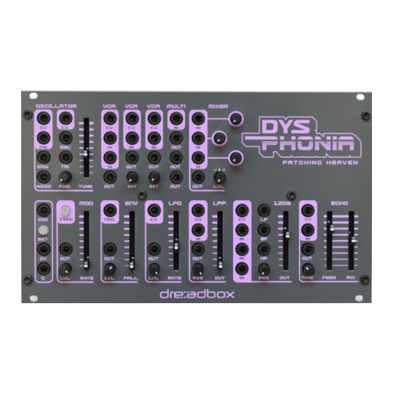
3. User's manual 3.1 Oscillator This is an analog oscillator with multiple wave shapes consists of: - Four dedicated outputs: Square Wave, Sawtooth, Triangle and Noise. - Two CV inputs for pitch control at 1V/oct. - A PW CV input for the Square wave. - A Tune slider for Coarse tuning. -
Page 23: Modulator (Mod)
3.6 Modulator (MOD) The Modulator section is a Digital multimode Modulator that consists of: a. A main OUT with a LVL control (+/-5V or 0-5V out depending on the mode) b. A TYPE button, which lets you choose from the different types available. The Types available are (in their cycling order): - LFO (range is from 0.05Hz up to 1.000Hz) - Sample and Hold (range is from 0.1Hz up to 1.000Hz) -
Page 24: Envelope (Env)
3.7 Envelope (ENV) The Envelope section is a digital Triggered envelope that consists of: - A Trigger input. - A main OUT with a LVL control. - A Slider, which controls the Fall Time. Holding the SET button while altering the FALL time controls the RISE time. -
Page 25: Specifications
4. Specifications - Length: 42HP (212mm) , Width: 3U (128,5mm) , Depth: 41mm (with the power board) , 33mm (without the power board) , Weight: 470 gr - All 3.5mm jacks expect a mono TS type cable, except for the - MIDI in, TRS type cable as suggested from the midi.org : https://www.midi.org/specifications/midi- transports-specifications -All pots are 100KB (linear), and sliders 10KB (linear) - Page 26 Input absolute max values: Even though the following values can be accepted, they must be avoided. Oscillator - CV : in +/-12V - PW : in +/- 12V VCAs - CV in : +/-12V - INPUT : +/- 8V MULTI - IN : +/-15V MIXER - IN : +/-12V...
- Page 27 Input optimal values: These are the optimal suggested values Oscillator - CV in : +/-10V - PW in : +/- 5V VCAs - CV in : +/-5V - INPUT : +/- 5V MULTI - IN : +/-10V MIXER - IN : +/-5V MIDI to CV - MIDI IN : typically 0-5v pulses - TRIG in : 0-5v pulse...
- Page 28 Output values: Oscillator - Waveforms : +/-5V. DC coupled - Noise: Up to +/-10V , depending on the trimming. Setup for +/-5V VCAs - OUT : unity gain with CV in at 5V, max is +/-10V with CV in at 10V. DC coupled MULTI - OUT = IN MIXER...
Need help?
Do you have a question about the Dysphonia and is the answer not in the manual?
Questions and answers