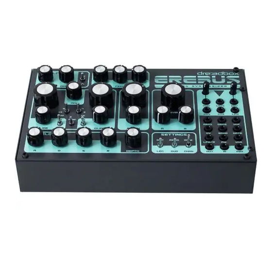
Dreadbox Erebus Construction Manual
Hide thumbs
Also See for Erebus:
- User manual (13 pages) ,
- User manual (16 pages) ,
- Owner's manual (9 pages)
Advertisement
Quick Links
In the box you will find:
- 3 x PCB boards
- The Aluminum panel
- A plastic bag with parts
- The metal enclosure
- A ribbon cable
- A DIN5 to 3,5mm MIDI Adapter
The plastic bag contains:
- 16 small knobs
- 4 large knobs
- 4 rubber feet
- A 2mm hex driver
- 14 M3 brass bolts
- 6 M3 black bolts
- 8 metal spacers 10mm length M3
- 1 plastic spacer
- 6 washers M3
- 20 pot washers
- 20 pot nuts M10
Additionally, you will need to have:
- A tuner
- A multimeter
- A 10mm HEX nut screwer
- A small straight screwdriver for trimming
- A larger straight screwdriver for the knobs
- A Philips PH1 screwdriver
- A USB adapter at least 1A of power
- A good USB cable
- A mini jack 3,5mm to 6,4mm
- A few patch cables 3,5mm
- A couple of crocks connectors
CONSTRUCTION
MANUAL
Advertisement

Summary of Contents for Dreadbox Erebus
- Page 1 CONSTRUCTION MANUAL In the box you will find: - 3 x PCB boards - The Aluminum panel - A plastic bag with parts - The metal enclosure - A ribbon cable - A DIN5 to 3,5mm MIDI Adapter The plastic bag contains: - 16 small knobs - 4 large knobs - 4 rubber feet...
- Page 2 Step 1 Place the 2 bolts as shown in the picture, so that the spacers are facing on the components side.
- Page 3 Step 2 Place the 4 bolts as shown in the picture, so that the spacers are not facing on the components side.
- Page 4 Step 3 Connect the panel with the board. Place all nuts and washers as shown in the picture and then bolt the 2 black bolts. While doing this do not apply too much force.
- Page 6 Step 4 Prepare the bottom PCB by attaching the holders for the power board.
- Page 7 Step 5 Connect the three boards. Be careful not to bend the headers while you attach them. Then bolt them in place.
- Page 9 Step 6 Attach the knobs to the potentiometers. All knobs have a set screw to the side. Use the straight screwdriver to firm them tightly as shown in the picture.
- Page 10 Step 7 - Tuning This is the most challenging part of the build. First thing you should do, is to prepare your workbench. Make sure that your working area is all cleaned up and we strongly suggest to use the foam to support the module.
- Page 11 7. While you are still on the calibration mode, set the LEG/OFF switch to LEG. 8. Remove the CV2 jack and the multimeter. We won’t be needing these anymore. 9. Connect the OUT to the TUNER. 10. Set up the synth as follow: - DO NOT TOUCH THE ENVELOPE AND THE GLIDE CONTROLS!!! - TUNE and DETUNE and MIX to exactly 50% - Both VCO waves and SYNC at OFF...
- Page 12 Step 8 Finalize the build by attaching the module to the enclosure. Attach the rubber feet, and then place the module into it. Make sure that the USB adapter is placed properly and then bolt the module into place with the 4 black bolts. Congratulations! Enjoy your new synthesizer!


Need help?
Do you have a question about the Erebus and is the answer not in the manual?
Questions and answers