Table of Contents
Advertisement
Quick Links
Advertisement
Table of Contents

Related Manuals for Metallkraft HLS 65 S


Summary of Contents for Metallkraft HLS 65 S
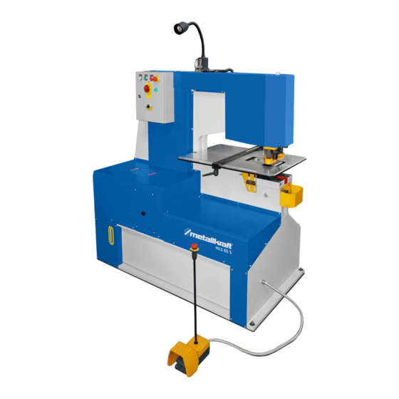
- Page 1 Operating Instructions Hydraulic hole punch HLS 65 S HLS 65 S...
- Page 2 Imprint Hydraulic hole punch Product identification Item number: 381 8065 HLS 65 S Stürmer Maschinen GmbH Manufacturer Dr.-Robert-Pfleger-Str. 26 D-96103 Hallstadt Fax: 0049 (0) 951 96555 - 55 E-Mail: info@metallkraft.de www.metallkraft.de URL: Genuine operating instructions Information about the operating instructions 08.05.2017...
-
Page 3: Table Of Contents
CONTENTS Page 4 - 3 General notes Work Station Technical Specifications 8 - 9 Transportation Safety explanations 10 - 12 13 - 15 Operation of the machine Punching Table Punching Tools 17 - 21 Electrical Informations Hydraulic System Lubrication Machine Rod and Lever readjustment Maintenance Table Optional Punch, DIE and Blade 26 - 29... -
Page 4: General Notes
GENERAL NOTES 1. Introduction Thank you for choosing this Metal Working Machine. We are proud to have you in our long list of satisfied customers all over the world. This User’s Manual is absolutely for your safety and is essential for the machine to have a long production life. - Page 5 2. Transport As soon as you receive the machine, check for any visible transport damages. Should there be any visible damages; report it straight away to the transporter company and of Stürmer Maschinen GmbH. Remove any protective crates around the machine and read the instructions on related chap-ters of this Manual carefully to set up the machine.
-
Page 6: Work Station
WORK STATION PUNCHING STATION All punching operating are processed by means of hydraulic power thus giving the machine the ability to punch very efficiently and silently. It can either be used to punch thick materials or thin materials in layers together. Punching is silent, powerful, efficient. The waste materials in layers together. The punching table consists two parts. -
Page 7: Technical Specifications
Technical specifications Pressure 65 t Ø in max.sheet thickness Ø26x20 mm / 57 x 10*** mm Reach 625 mm Stroke 55 mm Stroke / min. 22 min-1 950 mm Hole punch working height 5,5 kW Motor output 400 V / 50 Hz Electrical connections 1600x900x1800 Dimensions in mm... -
Page 8: Transportation
TRANSPORTATION There is a ring mounted on top of the machine for transport purposes. You mount the chain or rope to this ring for all kind of displacement purposes. DAMAGES As soon as you receive the machine, make a general check on the machine and inform the transporter and the manufacturer in case of any visible damage. - Page 9 SETTING UP THE MACHINE Ask for help of an experienced and qualified technician while setting up the machine 1-) Fundamental Plan of the Machine 5 holes ( Refer to the drawing below ) Dia : 15 mm 2-) Instructions For an effective machine, the position and the base of the machine are important. Be careful on these points while placing the machine: ...
-
Page 10: Safety Explanations
SAFETY EXPLANATIONS The HLS-65 S is equipped with a hydraulic check valve system in order to relieve the excess pressure when the machine is overloaded, thus preventing serious damage to the machine and the worker. All safety precautions are for your safety, which we believe will be obeyed by our customers unasked. - Page 11 All the safety components and fixing installations that should be removed for maintenance purposes, should be remounted again before the machine is reoperated. The operators should wear the clothing described by the employer. The producer recommend the use of protection eyeglasses against eventual stamp breaks and shoes with steel covering in order to prevent foot of the operator against falling materials.
- Page 12 The machine capacity shall never be exceeded. For this purpose, check the" technical data" on this rules and compare the values with the information given on the manufacture plate. All the capacity information is based on a material having a resistance of 45 kg/mm Should the hydraulic circuit flow be overloaded, the hydraulic oil will be led back to the reserve tank over the overload valve until the pressure gets down again to the normal level.
-
Page 13: Operation Of The Machine
OPERATION OF THE MACHINE Operation elements All the electrical delivery of the machine passes through the main switch. In order to connect this, rotate the switch clockwise. To confirm this, check that the control lamp starts lighten. By pressing on the green “START” button, connect the motor ( for the motor to be able to function, the “STOP”... - Page 14 PUNCH CAPACITY The diagram shows the punch capacity curves of the XS-series depending on the material thickness and stamp diameter. ( Based on a construction steel having a traction resistance of 45kg/mm Diameter of the punch stamp D (mm). During calculation of the punch capacity it should proceeded according to the following formula: P = SHEARING SURFACE x TRANTION RESISTANCE P = Π...
- Page 15 PRESS BRAKE BENDING Bar bending max. Capacity 250 x 20 mm Sheet bending max. Capacity 500 x 3 mm PIPE NOTCHING Max. Pipe diameter is Ø 108 mm - 15 -...
-
Page 16: Punching Table
PUNCHING TABLE In order to break the punching tool, you must use this table ( holder ) wisely. It must be always equaled and must be set for different pressures. The distance between lower table and material should be something between 1- 3 mm. Also to have the tool efficiently work the biggest part of the material should be covered by lower body during operation. -
Page 17: Punching Tools
PUNCHING TOOLS The part numbers in the above given figure 1 belong to the standard equipment. - 17 -... - Page 18 The parts indicated in the below given table belong to the standard equipment. Some different hole stamps and cutting cases are illustrated on the lateral drawing. As standard material, a 22 mm hole and cutting case delivered ( the maximum diameter amounts to 38 mm ).
- Page 19 ARRANGEMENT OF THE PUNCH TOOLS IN GENERAL The big punch bearing surface and removable front block have been constructed in manner to allow a very wide range punch works: Through the optionally obtained tools, the big holes in any form up to the diameter / quadrate as it is indicated in the capacity table can be produced.
- Page 20 In order to install or change the punch tools you will need the following tools: Hook key Soc. head cap bolt key ( 6 mm ) Screw key ( 24 mm ) WHILE ORDERING SPARE STAMPS AND MATRIXES, PLEASE ALWAYS INFORM OF THE FOLLOWING : MODEL, TYPE AND MANUFACTURING NUMBER OF THE MACHINE.
- Page 21 SAFETY PRECAUTIONS ON EACH OF THE WORK STATIONS IS WRIITEN UNDER ITS NAME WRONG CORRECT Wrong sized punch holder Wrong sized part Wrong distance Normal punching Very small punching, which requires special eccentric die and tool FLANGE PUNCHING You can use the standard tool for all kind of punching, however for flange punching like pictured above (right side), you have to order us a new set of eccentric die and tool.
-
Page 22: Electrical Informations
Electrical Information - 22 -... -
Page 23: Hydraulic System
HYDRAULIC SYSTEM A 5.5 kw motor drives a hydraulic pump, which supplies the power cylinders on each end of the machine through regulation valves. The punch cylinder is directly connected to the punching unit Hydraulic oil For this purpose are advised the oil types indicated in the machine plate. The oil filling and ventilation supports are located in the tank where access is provided after removal of the protection having cooling cavities located on machine base. -
Page 24: Lubrication
LUBRICATION HYDRAULIC FLUID Fill to top level of inspection glass. Use only mineral oil as recommended or equivalent. You can select a oil at the table 1 OILING LUBRICANT Check oil level in pump reservoir daily, operate pump 2/3 times daily. Castrol Magna DR220 Shell... -
Page 25: Machine Rod And Lever Readjustment
MACHINE ROD AND LEVER READJUSTMENT After a preliminary working period ( about 5 to 6 days ), it will be necessary to carry out arran- gement adjustments on the machine. Punch rod The arrangement of the rod will be realized with the help of a “rod leading plate”. ... -
Page 26: Optional Punch, Die And Blade
- 26 -... - Page 27 - 27 -...
- Page 28 - 28 -...
- Page 29 - 29 -...
-
Page 30: Special Accessories
SPECIAL ACCESSORIES Drilling of the I and U profiles During punching of the I profiles, change the standard scraper head with the lengthened type. Min. profile size 65 for I or U profile Max. profile size 120 for I or U profile PART DESCRIPTION QUANTITY Hole ring ( 5 - 38 ) usable with stamp... -
Page 31: Hydraulic Plan
HYDRAULIC PLAN 5.5 Kw 7.5 KW 400 V 400 V 50 Hz 50 Hz - 31 -... - Page 32 HYDRAULIC PLAN LİST HYDRAULIC SPARE PARTS LIST DESCRIPTION CODE IDENTITY OIL TANK 70 Lt LEVEL POWER SWITCH OIL TANK CAP EMİŞ FİLTRESİ GEAR PUMP 5140625022 ELECTRIC MOTOR 5,5KW / 1400 PRESSURE CONTROL VALVE 0811109133 DIRECTION CONTROL VALVE 4WE 10H33-CG24N9K DIRECTION VALVE 01MW9CN1W75 Ø180 Honlanmış...
-
Page 33: Spare Parts Drawing
Spare Parts drawing - 33 -... -
Page 34: Wiring Diagram
Wiring Diagram - 34 -... - Page 35 ® � •• etallkratt Metallbearbeitungsmaschinen 2. 9/6 -------��------,�------��-------------,, sa113" S02� .f-- 2 . 9/- _______________ J�--------------------� CODE EXPLANATION MAIN SWITCH MOTOR PROTECTION OVERLDAD THERMAL RELAY MOTOR CONTACTOR AUXILIRRY CONTACTS FOR MOTOR PROTE(TION OVERLORO THERMAL SWITCH TRANSFORMATOR +15/0/-15/230/400/440 0/12 0/24V ZOOVA BRIDGE DIODE FUSE TERMINAL...
-
Page 36: Eu-Declaration Of Conformity
According to Machinery,Directive 2006/42/, Annex II 1.A Stürmer Maschinen GmbH Manufacturer / distributor Dr.-Robert-Pfleger-Straße 26 D-96103 Hallstadt herebly declares that the following product Product Category: Metallkraft® Metallbearbeitungsmaschinen HLS 65 S Description: 3818065 Item number: Machine type: Hydraulic hole punch ____________________ Serial number:... -
Page 37: Notes
Notes - 37 -... - Page 38 www.metallkraft.de...
Need help?
Do you have a question about the HLS 65 S and is the answer not in the manual?
Questions and answers