Table of Contents
Advertisement
Quick Links
Advertisement
Table of Contents

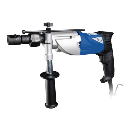
Summary of Contents for Metallkraft GS 18
- Page 1 Operating Instructions Tapping Power Tool GS 18 GS 18...
-
Page 2: Table Of Contents
Passing on as well as copying of this document, the use and distribution of its content are prohibited if not explic- itly permitted. Contraventions are liable to compensa- tion. Subject to technical modifications and error. GS 18 | Version 1.05... -
Page 3: Introduction
- Never bypass or override the safety devices. Spare part orders: Fax: 0049 (0) 951 96555-119 - Only operate the machine in a technically perfect E-Mail: ersatzteile@stuermer-maschinen.de condition. We are always interested in valuable experience and knowledge gained from using the application-which GS 18 | Version 1.05... -
Page 4: Safety
- The operator must provide the necessary protec- avoided. tive equipment to the staff and order the use of the necessary protective equipment in a binding way. GS 18 | Version 1.05... -
Page 5: Requirements To Staff
GS 18 | Version 1.05... -
Page 6: Safety Identifications On The Tapping Power Tool
45 ° to the horizontal. On-load speed during cutting pro- 170 U/min Avoid larger angles. Working overhead is ex- cess tremely dangerous and should be avoided. Slip clutch (Stall torque) 31,4-34,3 Nm GS 18 | Version 1.05... -
Page 7: Type Plate
The nameplate with the following data for identification as well as the CE marking are attached to the tap (fig. 2). Fig. 2: Type plate and CE-marking of the tap GS 18 Transport, package and storage 5.1 Delivery and transport The thread cutter must be checked after delivery for vis- ible transport damage and for completeness. -
Page 8: Description Of The Device
Description of the device 6.1 Illustration Illustrations in this operating manual serve the general under-standing and may deviate from the ac- tual design. Fig. 3: Description Tapping Power Tool GS 18 1 Locking screw 2 Turning head 3 Locking screw... -
Page 9: Operation
Connect the Tapping Power Tool to the mains in the fol- lowing steps: Fig. 4: Holder for taps Step 1: Check that the motor switch is off. Step 2: Plug in the mains plug into the 230V socket after clamping the tool. GS 18 | Version 1.05... -
Page 10: Drilling
Step 1: Place the tap on the workpiece and position the machine so that the tap is accurately centered on the center of the core hole. Step 2: Press the machine onto the workpiece to set the rotation direction for screwing in. GS 18 | Version 1.05... -
Page 11: Depth Stop
For this please wool in a suitable, closed container and dispose of contact our customer service (see 1.2). them in a manner suitable for environmentally- friendly disposal - do not dispose of with household waste! GS 18 | Version 1.05... -
Page 12: Maintenance
ATTENTION! Repairs or maintenance work may only be carried out by qualified and trained specialist personnel. Carbon brushes Fig. 7: ATTENTION! Always replace the carbon brushes in pairs. GS 18 | Version 1.05... -
Page 13: Disposal, Recycling Of Old Equipment
9.3 Disposal of lubricants Please pay attention to an environmentally friendly dis- posal of the used coolants and lubricants. Observe the disposal instructions of your municipal disposal compa- nies. The disposal instructions for the lubricants used GS 18 | Version 1.05... - Page 14 Spare parts Example The motor housing of the thread cutter GS 18 must be ordered. The motor housing has the position number 14 in the spare part drawing. - Type of device: Tapping Power Tool GS 18 - Item number: 3860018...
-
Page 15: Spare Part Drawing
In case of service, the following drawing shall help to identify the necessary spare parts. If necessary, send a copy of the parts drawing with the marked components to your authorized dealer. Fig. 9: Spare part drawing GS 18 GS 18 | Version 1.05... -
Page 16: Electrical Wiring Diagram
Electrical wiring diagram 12 Electrical wiring diagram Fig. 10: Electrical wiring diagram GS 18 GS 18 | Version 1.05... -
Page 17: Ec Declaration Of Conformity
Safety of machinery - Electrical equipment of machines - Part 1: General requirements DIN EN 61029-1:2009+A11:2010 Safety of transportable motor-operated electric tools Part 1: General requirements Kilian Stürmer, Dr.-Robert-Pfleger-Str. 26, D-96103 Hallstadt Responsible for documentation: Hallstadt, 20/07/2016 ______________________ Kilian Stürmer Manager GS 18 | Version 1.05... - Page 18 www.metallkraft.de...


Need help?
Do you have a question about the GS 18 and is the answer not in the manual?
Questions and answers