
Related Manuals for Metallkraft HPS DS Series


Summary of Contents for Metallkraft HPS DS Series
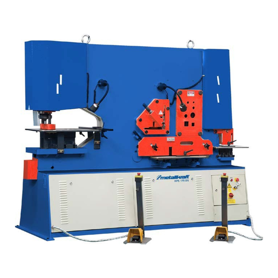
- Page 1 Operating Instructions Hydraulic section steel shears HPS 55 DS, HPS 65 DS, HPS 85 DS HPS 115 DS, HPS 175 DS...
-
Page 2: Table Of Contents
INDEX Page General notes Readjustment View of the delivery side Setting up the machine Technical specifications Additional tools Five work stations 10-11 Safety explanations 12-14 Operation of the machine Arrangement of the punch tools 16-18 Safety precautions on each of the work stations Angle cutting installation Mitring angle 45 degrees Profie cutting station... -
Page 3: General Notes
GENERAL NOTES 1. Introduction Thank you for choosing a METALLKRAFT Metal Working Machine. We are proud to have you in our long list of satisfied customers all over the world. This User’s Manual is absolutely for your safety and is essential for the machine to have a long production life. - Page 4 2. Transport As soon as you receive the machine, check for any visible transport damages. Should there be any visible damages; report it straight away to the transporter company and of course Stürmer Maschinen GmbH or your supplier. Remove any protective crates around the machine and read the instructions on related chap- ters of this Manual carefully to set up the machine.
-
Page 5: Readjustment
READJUSTMENT The adjustment of the shear levers should be carried out before any adjustment of the shear blade. The adjustment explain as shown below. Explanation of figure 1. Adjustment screw 2. Safety nut 3. Bronze pressure plate - 3 -... -
Page 6: View Of The Delivery Side
VIEW OF THE DELIVERY SIDE Punch cylinder Lever group Punch unit Punch unit Driver set hydraulic VIEW OF THE EXIT SIDE - 4 -... -
Page 7: Setting Up The Machine
SETTING UP THE MACHINE Ask for the help of an experienced and qualified technician while setting up the machine. 1) Fundamental Plan of the Machine Four holes (Refer to the drawing below) Dia.15mm 2) Instructions For an effective machine, the position and the base of the machine are important. Be careful on these points while placing the machine: ... -
Page 8: Technical Specifications
TECHNICAL SPECIFICATIONS General Information HPS 55 DS HPS 65 DS HPS 85 DS Motor Power 5,5 kW 5,5 kW 7,5 kW Pressure 55 t 65 t 85 t Operating Voltage 400 V/50 Hz 400 V/50 Hz 400 V/50 Hz Machine Dimensions 1500 x 950 x 1700 x 950 x 1920 x 950 x... - Page 9 Optional Tools HPS 55 DS HPS 65 DS HPS 85 DS U-I Section blades 120 x 58 mm 120 x 58 mm 160 x 74 mm T- Section blades 80 x 9 mm 90 x 11 mm 100 x 11 mm V-notching 100 x 100 x 10 100 x 100 x 10...
- Page 10 Sheet Metal Shear Sheet thickness max. 380 x 25 mm 380 x 30 mm Sheet size max. 600 x 15 mm 600 x 20 mm Blade lenght 610 mm 610 mm Shearing with angle 120 x 15 mm 120 x 15 mm Working height 935 mm 810 mm...
-
Page 11: Additional Tools
ADDITIONAL TOOLS BENDING [mm 2 ] 500x3 Maximum bar size PUNCHING AT THREADING STATION [mm 2 ] 38x8 Maximum capacity [mm 2 ] Groove depth NOTCHING [mm 3 ] 100x100x6 Maximum thread surface PIPE NOTCHING [mm] Maximum tube diameter Based on material strength 45 [kg/mm2] The maximum punching pressure of this machine is 650 kN ( 65 ton ) The following tools are included in the basic equipment of the machine;... -
Page 12: Five Work Stations
FIVE WORK STATIONS 1-PUNCHING STATION All punching operating are processed by means of hydraulic power thus giving the machine the ability to punch very efficiently and silently. It can either be used to punch thick materials or thin materials in layers together. Punching is silent, powerful and efficient. The waste materials in layers together. -
Page 13: Five Work Stations
PROFILE CUTTING STATION The machine are equipped as standard with the blades for cutting round and quadrangle bars. Through additional equipment, it is possible to cut at the machine U-section, I-section and T- section profiles in this clearance. The blades are held by simple squeezing jaws which ensure an easy equipment arrangement at the machine without any detailed adjustment. -
Page 14: Safety Explanations
These persons need to be essentially trained in terms of this subject. All the METALLKRAFT machines are delivered as standard with a safety equipment, such equipment is for a high and general work safety. For this purpose, the machine should only be used in accordance for those purposes for which it has been constructed. - Page 15 All the safety components and fixing installations that should be removed for maintenance purposes, should be remounted again before the machine is reoperated. The operators should wear the clothing described by the employer. The producer recommend the use of protection eyeglasses against eventual stamp breaks and shoes with steel covering in order to prevent foot of the operator against falling materials.
- Page 16 When you perform works where big forces are existing, the work piece should be additionally protected through a block having an assembled roll or similar installation, which is to be placed on the machine. The machine capacity shall never be exceeded. For this purpose, check the" technical data" on this rules and compare the values with the information given on the manufacture plate.
-
Page 17: Operation Of The Machine
OPERATION OF THE MACHINE Operation elements All the electrical delivery of the machine passes through the main switch. In order to connect this, rotate the switch clockwise. To confirm this, check that the control lamp starts lighten. By pressing on the green “START” button, connect the motor (for the motor to be able to function, the “STOP”... -
Page 18: Arrangement Of The Punch Tools
ARRANGEMENT OF THE PUNCH TOOLS IN GENERAL The big punch bearing surface and the removable front block have been constructed in manner to allow a very wide range punch works: Through the optionally obtained tools, the big holes in any form up to the diameter / quadrate as it is indicated in the capacity table can be produced. - Page 19 In order to install or change the punch tools you will need the following tools: Hook key Soc. head cap bolt key ( 6 mm ) Screw key ( 24 mm ) WHILE ORDERING SPARE STAMPS AND MATRIXES, PLEASE ALWAYS INFORM OF THE FOLLOWING: MODEL, TYPE AND MANUFACTURING NUMBER OF THE MACHINE.
- Page 20 PUNCH CAPACITY The diagram shows the punch capacity curves of the XS-series depending on the material thickness and stamp diameter. (Based on a construction steel having a traction resistance of 45kg/mm Diameter of the punch stamp D (mm). During calculation of the punch capacity it should proceeded according to the following formula: P = SHEARING SURFACE x TRANTION RESISTANCE P = ∏×D ×...
-
Page 21: Safety Precautions On Each Of The Work Stations
SAFETY PRECAUTIONS ON EACH OF THE WORK STATIONS IS WRIITEN UNDER ITS NAME WRONG CORRECT Wrong sized punch holder Wrong sized part Wrong distance Normal punching Very small punching, which requires special eccentric die and tool FLANGE PUNCHING You can use the standard tool for all kind of punching, however for flange punching like pictured above (right side), you have to order us a new set of eccentric die and tool. -
Page 22: Angle Cutting Installation
ANGLE CUTTING INSTALLATION This work station allows the cutting of big angles of 90 as well as cutting of the angles smaller than 45 In order to cut angle profiles, the material is placed into the cutting zone through the fixing installation and the support screw is adjusted to the corresponding material thickness. -
Page 23: Mitring Angle 45 Degrees
MITRING ANGLE 45 DEGREES Since the introduction of the requirements for health and safety, the accessibility and distance between hold-downs and blades have been amended. To this effect the operation cutting angle in the angle cutting station requires the following simple hold-down adjustment. -
Page 24: Profie Cutting Station
PROFIE CUTTING STATION SHEARING INSTALLATION Blade adjustment / Blade Change: During the installation of the new blades, pay attention to that the mobile blades fully approach onto the shear lever. While the machine is disconnected, pull blades together with the soc. head cap bolts (Nr.1) totally onto the shear lever. -
Page 25: Shearing, Profile Section Cutting
SHEARING, PROFILE SECTION CUTTING The shearing unit has been equipped with a simple and strong fixing installation that can be arranged at any material thickness within the cutting capacity of the machine. A shearing delivery table having adjustable quides has been constructed in order to allow a correct delivery of the material. The guiding can be arranged in a manner to allow the angle cuts up 45 for flat bar material or the cutting of flange of angle profiles, which have been previously cut at the inclined cutting station. -
Page 26: Notching Station
NOTCHING STATION The threading station has quadrangles punch stamp as a standard equipment element and is delivered with a threading table complete with adjustable lateral and rear counter holders, which essentially simplify the repeatable positioning of the material. The sharp notching tools can also be constructed at this work station. Optionally, the units for narrower width of quadrangles or forms can also be delivered. -
Page 27: Stroke Adjustment
STROKE ADJUSTMENT In order to lock the lowering stroke ( that means repeated bending etc. ) you must adjust the stropper A towards side. In order to lock the upper stroke B, use the punch stamp with the foot pedal and hold this in the lower position. -
Page 28: Hydraulic System
HYDRAULIC SYSTEM A 5.5 KW motor drives a hydraulic pump, which supplies the power cylinders on each end of the machine through regulation valves. The punch cylinder is directly connected to the punching unit, where the shear cylinder is connected through a turning lever. Hydraulic oil For this purpose are advised the oil types indicated in the machine plate. - Page 29 HYDRAULIC LUBRICATION HYDRAULIC FLUID Fill to top level of inspection glass. Use only mineral oil as recommended or equivalent. You can select a oil at the table 1 OILING LUBRICANT Check oil level in pump reservoir daily, operate pump 2/3 times daily. Castrol Magna DR220 Shell...
-
Page 30: Machine Rod And Lever Readjustment
MACHINE ROD AND LEVER READJUSTMENT After a preliminary working period (about 5 to 6 days), it will be necessary to carry out arran-gement adjustments on the machine. Punch rod The arrangement of the rod will be realized with the help of a “rod leading plate”. ... -
Page 31: Punch Tools
PUNCH TOOLS The part numbers in the above given figure 1belong to the standard equipment. - 29... -
Page 32: Punch Tool Part List
PUNCH TOOL PART LIST The parts indicated in the below given table belong to the standard equipment. Some different hole stamps and cutting cases are illustrated on the lateral drawing. As standard material, a Ø22 mm hole and cutting case delivered (the maximum diameter amounts to 38 mm). -
Page 33: Part And Parts List Of The Cutting Frame
PART AND PARTS LIST OF THE CUTTING FRAME PART DESCRIPTION QUANTITY Mobile profile blade Fixed profile blade Hook Soc. head cap bold Set screw Set screw Counter nut - 31... -
Page 34: Blade Adjustment / Blade Change
BLADE ADJUSTMENT / BLADE CHANGE During the installation of the new blades, pay attention to that the mobile blades fully approach onto the shear lever. While the machine is disconnected, pull blades together with the internal hexagonal screws (3) totally onto the machine body, without the thread pins (4) press against the blade. -
Page 35: Blade Part List
BLADE PART LIST SPECIAL PART DESCRIPTION QUANTITY Upper blade Lower blade Set screw Washer Spring washer Set screw Hex. soc. head cap bolt washer - 33... -
Page 36: Notching Parts
NOTCHING PARTS PART DESCRIPTION QTY. Scraper finger Upper blade Lower blade Lower blade Holder Tensioning Hex. Screw M12x65 Spring disc 12mm Flat disc 12 mm Nut M12 Internal hex. Screw M10x25 Internal hex. Screw M10x30 Maden screw M8x20 Internal hex. Screw M16x40 Flat disc M16 Nut M16 - 34... -
Page 37: Special Accessories
SPECIAL ACCESSORIES Drilling of the I and U profiles During punching of the I profiles, change the standard scraper head with the lengthened type. Min. profile size 65 for I or U profile Max. profile size 120 for I or U profile PART DESCRIPTION QUANTITY Hole ring ( 5 –... -
Page 38: True Punching
TRUE PUNCHING Figure 2 Figure 1 This machine is equipped with a single piston. When you work with the machine on shearing station with max shearing and then change to punching station the overtravel may cause the holding nut (A) to contact the scraper(B) and damage these components. -
Page 39: Hydraulic Plan
HYDRAULIC PLAN - 37... -
Page 40: Transportation
TRANSPORTATION There is a ring mounted on top of the machine for transport purposes. You mount the chain or rope to this ring for all kind of displacement purposes DAMAGES As soon as you receive the machine, make a general check on the machine anal inform the transporter and the manufacturer in case of any visible damage. -
Page 41: Ec Declaration Of Conformity
Manufacturer/distributor Dr.-Robert-Pfleger-Straße 26 D-96103 Hallstadt hereby declares that the following product ® Product Group: Metallkraft Metallbearbeitungsmaschinen HPS 55 DS, HPS 65 DS, HPS 85 DS Description of the machine: HPS 115 DS, HPS 175 DS Machine typ: Hydraulic section steel shears... - Page 42 www.metallkraft.de...
Need help?
Do you have a question about the HPS DS Series and is the answer not in the manual?
Questions and answers