Advertisement
Quick Links
Advertisement

Subscribe to Our Youtube Channel
Related Manuals for Brodersen GC-10


Summary of Contents for Brodersen GC-10
- Page 1 GC-10 Wireless Control Box Installation Guide 40204-27_04.p65 02-07-2004, 14:28...
- Page 2 EN/IEC61010-1, table J1. If the GC-10 is coupled with or fed by power- DIN VDE 0113 frequency voltage networks of overvoltage Electrical equipment of machines part 1:...
-
Page 3: Warning Cautions
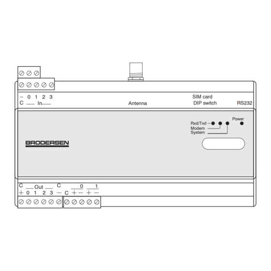
• GSM Emission nance, the product presents no danger to The operation of the GC-10 within the persons and objects under normal conditions. vicinity of inadequately protected personal medical devices, such as Brodersen Controls cannot accept any liaility... - Page 4 GC-10 Layout and dimension drawings 0 1 2 3 SIM card RS232 Antenna DIP switch Power Rxd/Txd Modem System 40204 -100/27.04 40204-27_04.p65 02-07-2004, 14:28...
- Page 5 GC-10 Mounting instruction The GC-10 is mounted on a 35mm DIN-rail (enclosed in the package). Mount the DIN rail on a wall or in a suitable panel or box. Note that you must have space for the antenna and wiring.
- Page 6 GC-10 Wiring Diagram - general Wire size Terminal blocks for I/O and power supply are Earth and power supply: max. 2,5mm (earth plug-in connectors with screw terminals. It is wiring must be 2,5mm and kept as short as recommended to use ferrules on wires.
- Page 7 GC-10 Power Supply Version 10 Version 50 Mains supply VDC supply Earthing: Connect to PE conductor - wire as short as possible. Version 10: L: 115-230VAC Mains supply N: 0V Mains supply (neutral). Version 50: +: +V DC positive 0V negative Supply output Supply for I/O etc.
- Page 8 GC-10 Digital Input To activate the inputs an external voltage is required, use e.g. the 12V supply from the GC-10. Must be connected via potential free contacts. Analogue input External supply 10 - 30V DC Analogue input (Pt-100 sensor input) 1 Pt-100 sensor input.
- Page 9 GC-10 I/O Wiring examples Switch wired to first digital input: 0 1 2 3 SIM card Antenna DIP switch RS232 Power Rxd/Txd Modem System UCR-10IO First control output for switching 230V AC via relay: 0 1 2 3 SIM card...
- Page 10 4-20mA mended to keep the total damping for cable below 10dB. Note: GC-10 must NOT be power up with- Option 2 - Not loop powered transmitter (4- out antenna. Powering up without antenna or 20mA or 0-10V).
- Page 11 Application ground wiring An protective ground back plane is recom- mended in the panel. The GND terminal on the GC-10 and the DIN rail must be con- nected direct to the grounded back plane. 0 1 2 3 SIM card...
- Page 12 DIP switch RS232 System Rxd/Txd Modem Power Rxd/Txd LED: Indicators 4 LEDs are placed on the front of the GC-10. Indicate RX/TX communication activity to modem interface. System LED: Application program running OK Off= Application program error Flashing = General Error.
Need help?
Do you have a question about the GC-10 and is the answer not in the manual?
Questions and answers