Table of Contents

Related Manuals for GORMAN-RUPP PUMPS T2A60 B


Summary of Contents for GORMAN-RUPP PUMPS T2A60 B
- Page 1 OM-05137-01 August 1, 2000 Rev. H 05‐12‐22 INSTALLATION, OPERATION, AND MAINTENANCE MANUAL WITH PARTS LIST T SERIESr PUMPS MODELS T2A60‐B INCLUDING: /F, /FM and /WW GORMAN‐RUPP PUMPS www.grpumps.com 2000 Gorman‐Rupp Pumps Printed in U.S.A.
- Page 2 Register your new Gorman‐Rupp pump online at www.grpumps.com Valid serial number and e‐mail address required. RECORD YOUR PUMP MODEL AND SERIAL NUMBER Please record your pump model and serial number in the spaces provided below. Your Gorman‐Rupp distributor needs this information when you require parts or service. Pump Model: Serial Number:...
-
Page 3: Table Of Contents
TABLE OF CONTENTS INTRODUCTION ..........PAGE I - 1 SAFETY - SECTION A . - Page 4 TABLE OF CONTENTS (continued) TROUBLESHOOTING - SECTION D ......PAGE D - 1 PREVENTIVE MAINTENANCE .
-
Page 5: Introduction
T SERIES OM-05137 INTRODUCTION Thank You for purchasing a Gorman‐Rupp pump. HAZARD AND INSTRUCTION Read this manual carefully to learn how to safely DEFINITIONS install and operate your pump. Failure to do so could result in personal injury or damage to the The following are used to alert maintenance per... -
Page 6: Safety - Section A
T SERIES OM-05137 SAFETY - SECTION A This information applies to T Seriesr ba 6. Vent the pump slowly and cau sic pumps. Gorman‐Rupp has no con tiously. trol over or particular knowledge of the 7. Drain the pump. power source which will be used. Refer to the manual accompanying the power source before attempting to begin op... - Page 7 OM-05137 T SERIES charge valve, pump components will hoists, chains, slings or cables are in deteriorate, and the liquid could come good working condition and of suffi to a boil, build pressure, and cause the cient capacity and that they are posi pump casing to rupture or explode.
-
Page 8: Installation - Section B
T SERIES OM-05137 INSTALLATION - SECTION B Review all SAFETY information in Section A. specific application. Since the pressure supplied to the pump is critical to performance and safety, Since pump installations are seldom identical, this be sure to limit the incoming pressure to 50% of section offers only general recommendations and the maximum permissible operating pressure as practices required to inspect, position, and ar... -
Page 9: Positioning Pump
OM-05137 T SERIES ing, check for loose hardware at mating sur and the pump or components will not be faces. damaged when lifting. Suction and dis charge hoses and piping must be re c. Carefully read all warnings and cautions con moved from the pump before lifting. -
Page 10: Line Configuration
T SERIES OM-05137 compatible with the liquid being pumped. If hose is Fittings used in suction lines, it must be the rigid‐wall, rein Suction lines should be the same size as the pump forced type to prevent collapse under suction. Us inlet. -
Page 11: Suction Line Positioning
OM-05137 T SERIES If it is necessary to position inflow close to the suc Suction Line Positioning tion inlet, install a baffle between the inflow and the The depth of submergence of the suction line is suction inlet at a distance 1 1/2 times the diameter critical to efficient pump operation. -
Page 12: Bypass Lines
T SERIES OM-05137 In high discharge head applications (more than 30 feet), an excessive amount of liquid may be by passed and forced back to the wet well under the full working pressure of the pump; this will reduce If the application involves a high discharge overall pumping efficiency. -
Page 13: Automatic Air Release Valve
OM-05137 T SERIES tion when removing the plug to prevent liters] per minute) will occur when the valve is fully closed. Be sure the bypass injury to personnel from hot liquid. line is directed back to the wet well or tank to prevent hazardous spills. -
Page 14: Alignment
T SERIES OM-05137 The coupling is in alignment when the hub ends ALIGNMENT are the same distance apart at all points (see Fig ure 4A). The alignment of the pump and its power source is critical for trouble‐free mechanical operation. In ei ther a flexible coupling or V‐belt driven system, the driver and pump must be mounted so that their shafts are aligned with and parallel to each other. - Page 15 OM-05137 T SERIES Do not operate the pump without the guard in place over the rotating parts exposed rotating parts can catch cloth ing, fingers, or tools, causing severe in jury to personnel. MISALIGNED: MISALIGNED: ALIGNED: SHAFTS SHAFTS SHAFTS PARALLEL AND NOT PARALLEL NOT IN LINE SHEAVES IN LINE...
-
Page 16: Operation - Section C
OM-05137 T‐SERIES OPERATION - SECTION C Review all SAFETY information in Section A. 2. The pump has not been used for a consider able length of time. Follow the instructions on all tags, labels and de 3. The liquid in the pump casing has evapo cals attached to the pump. -
Page 17: Operation
OM-05137 T‐SERIES incorrect on a single‐phase motor, consult the liter Leakage ature supplied with the motor for specific instruc tions. No leakage should be visible at pump mating sur faces, or at pump connections or fittings. Keep all line connections and fittings tight to maintain maxi OPERATION mum pump efficiency. -
Page 18: Strainer Check
OM-05137 T‐SERIES Strainer Check If a suction strainer has been shipped with the pump or installed by the user, check the strainer If the application involves a high discharge regularly, and clean it as necessary. The strainer head, gradually close the discharge throt should also be checked if pump flow rate begins to tling valve before stopping the pump. - Page 19 OM-05137 T‐SERIES curately by placing a contact‐type thermometer AND REPAIR). Bearing overheating can also be against the housing. Record this temperature for caused by shaft misalignment and/or excessive vi future reference. bration. A sudden increase in bearing temperature is a warning that the bearings are at the point of failing When pumps are first started, the bearings may to operate properly.
- Page 20 T SERIES OM-05137 TROUBLESHOOTING - SECTION D Review all SAFETY information in Section A. Before attempting to open or service the pump: 1. Familiarize yourself with this manual. 2. Lock out or disconnect the power source to ensure that the pump will remain inoperative.
- Page 21 OM-05137 T SERIES TROUBLE POSSIBLE CAUSE PROBABLE REMEDY PUMP STOPS OR Strainer clogged. Check strainer and clean if neces FAILS TO DELIVER sary. RATED FLOW OR PRESSURE Suction intake not submerged at Check installation and correct sub proper level or sump too small. mergence as needed.
- Page 22 T SERIES OM-05137 TROUBLE POSSIBLE CAUSE PROBABLE REMEDY BEARINGS RUN Bearing temperature is high, but Check bearing temperature regu TOO HOT within limits. larly to monitor any increase. Low or incorrect lubricant. Check for proper type and level of lubricant. Suction and discharge lines not Check piping installation for properly supported.
- Page 23 OM-05137 T SERIES Preventive Maintenance Schedule Service Interval* Item Daily Weekly Monthly Semi‐ Annually Annually General Condition (Temperature, Unusual Noises or Vibrations, Cracks, Leaks, Loose Hardware, Etc.) Pump Performance (Gauges, Speed, Flow) Bearing Lubrication Seal Lubrication (And Packing Adjustment, If So Equipped) V‐Belts (If So Equipped) Air Release Valve Plunger Rod (If So Equipped) Front Impeller Clearance (Wear Plate)
- Page 24 OM-05137 T SERIES PUMP MAINTENANCE AND REPAIR - SECTION E MAINTENANCE AND REPAIR OF THE WEARING PARTS OF THE PUMP WILL MAINTAIN PEAK OPERATING PERFORMANCE. STANDARD PERFORMANCE FOR PUMP MODEL T2A60-B, Including /F, /FM, /WW Based on 70 F (21 C) clear water at sea level Contact the Gorman‐Rupp Company to verify per...
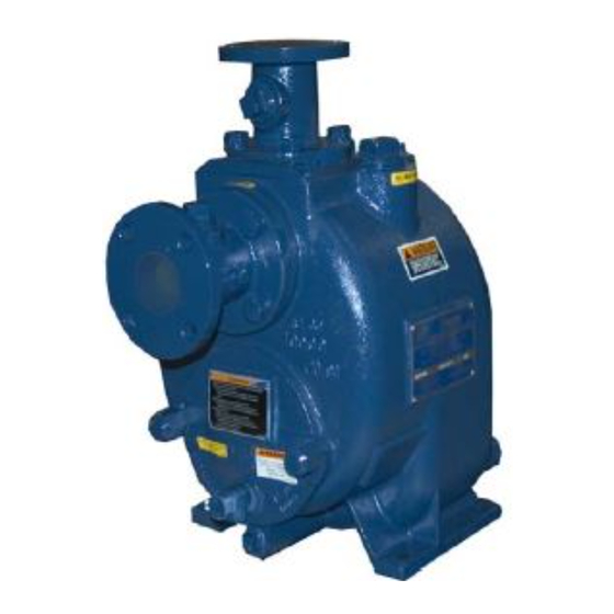
- Page 25 OM-05137 T SERIES PARTS PAGE ILLUSTRATION Figure 1. Pump Model T2A60-B, Including /F, /FM, /WW PAGE E - 2 MAINTENANCE & REPAIR...
- Page 26 OM-05137 T SERIES PARTS LIST Pump Model T2A60-B, Including /F, /FM, /WW (From S/N 1206376 Up) If your pump serial number is followed by an “N”, your pump is NOT a standard production model. Contact the Gorman‐Rupp Company to verify part numbers. ITEM PART NAME PART...
- Page 27 OM-05137 T SERIES ILLUSTRATION Figure 2. Repair Rotating Assemblies PAGE E - 4 MAINTENANCE & REPAIR...
- Page 28 OM-05137 T SERIES PARTS LIST Repair Rotating Assemblies Note: Order complete Repair Rotating Assemblies from the Pump Model Assembly Parts List on page E-3. Repair Rotating Assembly for /WW models include all of the standard parts listed below. ITEM PART NAME PART ITEM PART NAME...
- Page 29 OM-05137 T SERIES PUMP AND SEAL DISASSEMBLY AND REASSEMBLY Before attempting to open or service the pump: Review all SAFETY information in Section A. 1. Familiarize yourself with this man ual. Follow the instructions on all tags, label and decals 2.
- Page 30 T SERIES OM-05137 the tapped holes in the cover plate. Use these jack With the impeller rotation still blocked, see Figure 3 ing screws to remove the back cover and as and use a long piece of heavy bar stock to pry sembled wear plate from the pump casing (1).
- Page 31 OM-05137 T SERIES sion on the shaft seal spring will be released as the assembly. Disassemble the shaft and bearings impeller is removed. Inspect the impeller and re only when there is evidence of wear or damage. place it if cracked or badly worn. Remove the impeller adjusting shims (2);...
- Page 32 T SERIES OM-05137 Clean the bearings thoroughly in fresh cleaning small nicks and burrs with a fine file or emery cloth. solvent. Dry the bearings with filtered compressed Replace the shaft if defective. air and coat with light oil. Position the inboard oil seal (16) in the bearing housing bore with the lip positioned as shown in Figure 2.
- Page 33 OM-05137 T SERIES If heating the bearings is not practical, use a suit flammable. Use them only in a well ven ably sized sleeve and an arbor (or hydraulic) press tilated area free from excessive heat, to install the bearings on the shaft. sparks, and flame.
- Page 34 T SERIES OM-05137 RETAINER SEAL PLATE SPRING O‐RINGS IMPELLER IMPELLER SHIMS SHAFT SLEEVE O‐RING IMPELLER SHAFT INTEGRAL STATIONARY SHAFT ROTATING ELEMENT SLEEVE ELEMENT BELLOWS STATIONARY SEAT DRIVE BAND Figure 4. Seal Assembly cal or duct tape. Slide the O‐ring over the shaft until it seats against the shaft shoulder.
- Page 35 OM-05137 T SERIES Proceed with Impeller Installation and Adjust ment. Impeller Installation and Adjustment A new seal assembly should be installed (Figure 2) any time the old seal is removed from the pump. Wear patterns on the finished faces Inspect the impeller and replace it if cracked or cannot be realigned during reassembly.
- Page 36 T SERIES OM-05137 and install the impeller washer (26) and capscrew; Position the check valve in the mounting slot in the torque the capscrew to 90 ft. lbs. (1080 in. lbs. or pump casing (1) with the grooves in the rubber to 12,4 m.
- Page 37 OM-05137 T SERIES It is recommended that the pressure relief valve as ounces (0,35 liter) of SAE No. 30 non‐detergent oil. sembly be replaced at each overhaul, or any time Clean and reinstall the vented plug. Check the oil the pump overheats and activates the valve. Never level regularly through the sight gauge (10A) and replace this valve with a substitute which has not maintain it at the middle of the gauge.
- Page 38 For Warranty Information, Please Visit www.grpumps.com/warranty or call: U.S.: 419-755-1280 Canada: 519-631-2870 International: +1-419-755-1352 GORMAN‐RUPP PUMPS...
Need help?
Do you have a question about the T2A60 B and is the answer not in the manual?
Questions and answers