Table of Contents
Advertisement
Quick Links
Advertisement
Table of Contents

Subscribe to Our Youtube Channel
Related Manuals for ATX AIOT0-W680


Summary of Contents for ATX AIOT0-W680
- Page 1 AIOT0-W680 AIOT0-W680D Version 1.0...
- Page 2 Disclaimer The content of this manual is the intellectual property of the Company, and the copyright belongs to the Company. The ownership of all parts of this product, including accessories and software, is vested in the Company. Without the written permission of the Company, this manual and its any content shall not be imitated, copied, extracted or translated into other languages in any form.
-
Page 3: Table Of Contents
Contents Chapter 1 Summary ..............................1 Packing list ................................1 Motherboard specifications ..........................2 Structure drawing of motherboard ........................4 IO interface structure drawing of motherboard ....................5 Motherboard layout .............................. 5 IO panel interface ..............................6 Chapter 2 Hardware installation ........................... 7 Install CPU ................................ -
Page 5: Chapter 1 Summary
Chapter 1 Summary 1.1 Packing list Thank you for choosing our products. Please kindly confirm the integrity of the packaging of the motherboard you purchased. If there is any packaging damage or any shortage of accessories, please contact your dealer as soon as possible. ★... -
Page 6: Motherboard Specifications
RS232) 1 * 16-bit digital I/O with isolation, provides power source and ground circuit, +5V Digital I/O level ATX power source, supports ATX/AT On/Off mode Power source W680: 1 * PCIe x16 slot, supports PCIe 5.0 Maximum data bandwidth is 64GB/s;... - Page 7 Atmospheric Temperature -40°C-85°C; RH 5%-95% (40℃), BP 85-105kPa conditions of storage environment 255-level programmable in the mode of seconds/minutes, supports timeout interrupt Watch Dog or system reset AMI UEFI BIOS BIOS Win10 x 64,Win11 x 64,Linux Ubuntu 22.04 Operating System 305mm x 244mm PCB size...
-
Page 8: Structure Drawing Of Motherboard
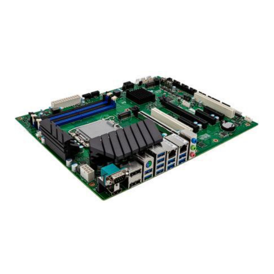
1.3 Structure drawing of motherboard... -
Page 9: Io Interface Structure Drawing Of Motherboard
1.4 IO interface structure drawing of motherboard 1.5 Motherboard layout (This image is for reference only, please prevail in kind) -
Page 10: Io Panel Interface
1.6 IO panel interface (This image is for reference only, please prevail in kind) COM: Serial port HDMI: HDMI display interface DP: DP display interface PS2: Keyboard & mouse interface USB3.0: USB3.0 interface LAN: RJ45 Ethernet interface ... -
Page 11: Chapter 2 Hardware Installation
Chapter 2 Hardware installation 2.1 Install CPU Before installing memory, please observe the following warning information: Please make sure that the CPU you purchased is compatible with the specifications supported by this motherboard. Before installing or removing the CPU, please make sure that the computer power is turned off to prevent damage. -
Page 12: Install Memory
2.2 Install memory Before installing memory, please observe the following warning information: Please make sure that the memory you purchased is compatible with the specifications supported by this motherboard. Before installing or removing memory, please make sure that the computer power is turned off to prevent damage. -
Page 13: Connect Peripherals
2.3 Connect peripherals 2.3.1 Serial ATA connector The interface supports the connection to Serial ATA hard disk or other devices that comply with the Serial ATA specification with Serial ATA flat cable. 2.3.2 M2-KEYM1/2 slot slot, supports SSD. When installing this card, please insert the card at an angle of 30°, press down to the stud, and then fix it with screws. -
Page 14: Pcie1/2/3/4/5/Pci1/2 Slots
2.3.3 PCIE1/2/3/4/5/PCI1/2 slots 1 * PCIe x16 slot , supports PCIe 5.0 1 * PCIe x16 slot, (x4 signals), supports PCIe 4.0 1 * PCIe x4 slot , supports PCIe 4.0 2 * PCIe x4 slot , supports PCIe 3.0 2 * standard PCI slot (32bit) -
Page 15: Chapter 3 Installation And Setup Of Jumpers & Connectors
BIOS settings, and restore the default factory settings) Definition Definition Disable ME NORMAL NORMAL 2-3 CLEAR_COMS ATX-M1 jumper setup (1-2: normal mode, press the power button to boot after being electrified; 2-3: automatically boot after being electrified) Definition ATX Mode AT Mode COM1 setup... -
Page 16: Atxpwr1 Power Interface (Standard 24Pin Power Interface)
3.3 ATXPWR1 power interface (standard 24Pin power interface) Pin Definition Pin Definition of pin of pin +3.3V +3.3V +3.3V -12V PSON# 5VSB +12V +12V +3.3V 3.4 PWR12V1 power interface (standard 8Pin power interface) Pin Definition of Pin Definition of pin +12V +12V +12V... -
Page 17: Cpu_Fan1 Interface (Cpu Fan Interface)
3.5 CPU_FAN1 interface (CPU fan interface) Pin Definition of +12V FAN_TAC FAN_CTL 3.6 JDV1 pin interface Definition Pin Definition of pin of pin CLK+ CLK- DDC SDA 18 DDC CLK... -
Page 18: Sys_Fan1/2 Pin Interface (System Fan Interface)
3.7 SYS_FAN1/2 pin interface (system fan interface) Definition of +12V FAN_TAC FAN_CTL 3.8 F_AUDIO1 pin interface (audio interface) Definition of Pin Definition of pin MIC2_IN_L MIC2_IN_R LINE2_OUT_R MIC2_JD LINE2_OUT_L LINE2_JD... -
Page 19: J_Gpio1 Pin Interface (Gpio Interface)
3.9 J_GPIO1 pin interface (GPIO interface) Pin Definition of Pin Definition of pin GPIO1 GPIO2 GPIO3 GPIO4 GPIO5 GPIO6 GPIO7 GPIO8 GPIO9 GPIO10 GPIO11 GPIO12 GPIO13 GPIO14 GPIO15 GPIO16 3.10 LPT1 pin interface (printer interface) Pin Definition Pin Definition of pin of pin LPT_STB LPT_AFD... -
Page 20: Com1 Pin Interface (Serial Port)
3.11 COM1 pin interface (serial port) Pin RS232 RS422 RS485 Definition Definition Definition of pin of pin of pin DCD# DATA- DATA+ DTR# DSR# RTS# CTS# Note: COM1, and JCOM2 serial ports need to be switched among RS232, RS422 or RS485 through the jumper setup. -
Page 21: Jespi1 Pin Interface
3.13 JESPI1 pin interface Pin Definition of Definition of pin +3.3V ESPI_IO0 ESPI_CS ESPI_IO1 ESPI_CLK ESPI_IO2 ESPI_RST ESPI_IO3 PLTRST 11 ESPI_ALERT 12 3.14 F_USB1/2 pin interface (USB interface) F_USB1 2.54 mm pin interface Pin Definition Pin Definition of pin of pin F_USB2 2.00 mm pin interface Pin Definition Pin Definition... -
Page 22: Fpanel1/2 Pin Interface
3.15 FPANEL1/2 pin interface FPANEL1 2.54 mm pin interface Pin Definition Pin Definition of pin of pin 1 HDD_LED+ 2 PWR_LED+ HDD_LED- PWR_LED- PWR_SW SYS_RST FPANEL2 2.00 mm pin interface Pin Definition Pin Definition of pin of pin PWR_ON HD_LED- HD_LED+ PWR_LED- PWR_LED+... -
Page 23: Chapter 4 Bios Settings
Chapter 4 BIOS settings 4.1 BIOS explanation This motherboard uses AMI BIOS. The full name of BIOS is Basic Input Output System. It is stored in a ROM (Read-Only Memory) chip on the computer motherboard. When you turn on your computer, BIOS is the first program to run. -
Page 24: Main
4.3 Main BIOS Information (BIOS related information) System Date (system date setting) Set the date of the computer in the format of “day of the week, month/day/year”. System Time (system time setting) Time format is <hour><minute><second>. 4.4 Advanced... - Page 25 CPU Configuration Press <Enter> key to enter the sub-menu Intel(R) SpeedStep(tm) Allow or not allow to support more than two frequency ranges. Options: Enabled,Disabled. Turbo Mode Set Turbo mode of professor. Options: Enabled,Disabled. Intel (VMX) Virtualization Technology ...
- Page 26 SATA Configuration Press <Enter> key to enter the sub-menu. SATA Controller Enable or disable Intel MVX technology. Options: Enabled,Disabled. VMD setup menu Setup menu for VMD. Hybrid Storage Detection and Configuration Mode Set the hybrid storage detection and configuration mode Options: Dynamic Configuration for Hybrid storane Enable, Disabled.
- Page 27 VMD setup menu Press <Enter> key to enter the sub-menu. Enable VMD controller Enable or disable VMD controller. Options: Enabled,Disabled. Press <Esc> key to return to “Advanced” main menu Onboard Devices Configuration Press <Enter> key to enter the sub-menu. ...
- Page 28 IT8786 Super IO Configuration Configure IT8786 super IO. Trusted Computing Configure the trusted computing. PPT Configuration Configure the PPT. Onboard Audio Enable or disable audio interface of motherboard. Options: Enabled,Disabled. PCH LAN Controller(I219) Set the PCH LAN controller. Options: Enabled,Disabled.
- Page 29 Trusted Computing Configuration Press <Enter> key to enter the sub-menu Security Device Support Set the BIOS support of security device. Options: Enabled,Disabled. SHA256 PCR Bank Enable or disable SHA256 PCR Bank. Options: Enabled,Disabled. Pending operation Set the pending operation. Options: None, TPM Clear.
- Page 30 PTT Configuration Press <Enter> key to enter the sub-menu TPM Device Selection Select the TPM device. Options: dTPM,PTT,Auto. Press <Esc> key to return to “Advanced” main menu Power Management Configuration Press <Enter> key to enter the sub-menu. ...
- Page 31 Restore AC Power Loss Set the status of AC power. Options: Power Off,Power On,Last State. WakeonLAN Enable or disable LAN. Options: Enabled,Disabled. PS/2KeyboardWakeUp Enable or disable PS/ 2 keyboard. Options: Enabled,Disabled. PS/2MouseWakeUp Enable or disable PS/ 2 mouse. Options: Enabled,Disabled.
- Page 32 Press <Esc> key to return to “Advanced” main menu Hardware Monitor Press <Enter> key to enter the sub-menu SYS Smart Fan2/1 Smart fan speed control of the system. Options: Full on Mode,Automatic Mode,Manual Mode. Temperature source select ...
- Page 33 NVMe Configuration Press <Enter> key to enter the sub-menu Note: When the motherboard is connected to NVMe, there is device displayed on the configuration interface of NVMe. Press <Esc> key to return to “Advanced” main menu Network Stack Configuration Press <Enter> key to enter the sub-menu ...
-
Page 34: Chipset
4.5 Chipset Internal Graphics Set the internal graphics. Options: Auto,Disable,Enable. Primary Display Display the default settings of onboard integrated and independent graphics. Options: Auto,IGFX,PEG Slot. Memory Configuration Set the memory. -
Page 35: Security
4.6 Security Administrator Password If this option is used to set the system administrator password, there are the following steps: Select the Administrator Password setting item, and press <Enter> key. Enter 3 to 20 character or numeric passwords to be set in the “Create New Password” dialog box. After the input is completed, press <Enter>... -
Page 36: Boot
4.7 Boot Setup Prompt Timeout Set the time of stay on the power-on screen. Bootup NumLock State Set the Numlock state after the system is started. When set to On, NumLock will be enabled and the number keys on the small keyboard will be valid after the system is started. When set to Off, NumLock will be disabled and the direction keys on the small keyboard will be valid after the system is started. -
Page 37: Save & Exit
4.8 Save & Exit Save Changes and Reset Save the changes and reboot the system. Discard Changes and Reset Discard the changes and reboot the system. Restore Defaults Restore and load all option defaults. -
Page 38: Chapter 5 Install Driver
Chapter 5 Install driver Please insert the motherboard driver disk into the CD-ROM drive, the driver disk will run automatically and then a pop-up interface will appear as shown below. If this interface does not appear, please double click to run X: \AUTORUN.EXE (assuming the symbol of driver disk is X: ). -
Page 39: Chapter 6 Wdt Programming Guide
Chapter 6 WDT programming guide 6.1 Description about programming guide document WDT control registers are located in LDN DEV7 of the SIO chip, where 0X72 BIT7 refers to the control by second and minute, 1 represents second and 0 represents minute, 0XF3 is filled with the time. For example, 0X72 BIT7 is 1, and 0XF3 is filled with 0X20, representing the overflow time of 32 seconds. - Page 40 IoWrite8(SioIndexPort, 0x72); IoWrite8(SioDataPort, temp_data); //Clear Status IoWrite8(SioIndexPort, 0x71); temp_data = IoRead8(SioDataPort); temp_data &= 0xfe; IoWrite8(SioIndexPort, 0x71); IoWrite8(SioDataPort, temp_data); //Count IoWrite8(SioIndexPort, 0x74); IoWrite8(SioDataPort, 0x0); IoWrite8(SioIndexPort, 0x73); IoWrite8(SioDataPort, ite_watch_dog_element->wdt_time); //printf("wdt start:%x\n",IoRead8(data));...
-
Page 41: Clear Watch Dog
6.1.2 Clear watch dog //wdt stop if(ite_watch_dog_element->wdt_operator==STOP_WDT){ IoWrite8(SioIndexPort, 0x74); IoWrite8(SioDataPort, 0x0); IoWrite8(SioIndexPort, 0x73); IoWrite8(SioDataPort, 0x0);... -
Page 42: Chapter 7 Gpio Programming Guide
Chapter 7 GPIO programming guide 7.1 GPIO control The hardware uses the GPIO pins with FINTEK 7511 expansion, the pins corresponding to 7511 are shown in the blow figure, and the communication is subject to PCHSMBUS control based on FINTEK 7511. 7.1.1 FINTEK 7511 SPEC... -
Page 43: Order Information
Order information Product model Chipset Memory Display Storage USB3 USB2 COM PCIe AIoT0-W680 W680 4 DDR5 4(4) 4SATA AIoT0-W680D W680 4 DDR5 4(4) 4SATA... -
Page 44: Marking For Toxic And Harmful Substances Or Elements In This Product
According to the requirements of SJ/T11364-2014 Measures for the Control of Pollution from Electronic Information Products issued by the Ministry of Information Industry of the People’s Republic of China, the marking for the pollution control of this product and the marking for toxic and harmful substances or elements in this product are as follows: Marking for toxic and harmful substances or elements in this product:...
Need help?
Do you have a question about the AIOT0-W680 and is the answer not in the manual?
Questions and answers