Table of Contents
Advertisement
Quick Links
Advertisement
Table of Contents

Subscribe to Our Youtube Channel
Related Manuals for ATX ULi M1689


Summary of Contents for ATX ULi M1689
- Page 1 ULi M1689 ATX Motherboard User’s Guide...
-
Page 2: Declaration Of Conformity
Declaration of Conformity According to 47 CFR, Parts 2 and 15 of the FCC Rules The following designated product: EQUIPMENT: MAINBOARD is a Class B digital device that complies with 47 CFR Parts 2 and 15 of the FCC Rules. Operation is subject to the following two conditions: 1. -
Page 3: Federal Communications Commission Statement
Federal Communications Commission Statement This device complies with FCC Rules Part 15. Operation is subject to the following two conditions: * This device may not cause harmful interference. * This device must accept any interference received, including interference that may cause undesired operation. This equipment has been tested and found to comply with the limits for a Class B digital device, pursuant to Part 15 of the FCC Rules. -
Page 4: Table Of Contents
TABLE OF CONTENTS Chapter 1 Introduction............1 1-1 Specifications ....................1 1-2 Package Contents ..................2 1-3 Back Panel ....................3 1-4 Motherboard Layout..................3 Chapter 2 Hardware Setup .............4 2-1 PC D.I.Y. Assembly Instructions..............4 2-2 自行組裝電腦之作業指導重點 (Chinese)..........6 2-3 Français Instructions de montage du PC D.I.Y (French)........8 2-4 Deutsch PC D.I.Y.-Montageanleitung (German) .........10 2-5 Самостоятельная... -
Page 5: Chapter 1 Introduction
1-1 Specifications - Supports AMD Socket-939 Althon 64 / Sempron CPU - Processor interface via 2000MT/s HyperTransport bus Chipset - ULi M1689 Memory - Four 184- pin DDR DIMMs up to 4GB - Supports Dual Channel DDR266/333/400 memory Due to CPU specifications limitation, two DDR400 memory modules inserted into DIMM1/3, three DDR400 into DIMM1/2/3, or four DDR400 into DIMM1/2/3/4 is not recommended. -
Page 6: Package Contents
8x2 pin Game/Midi Port connector 20 pin ATX Power connector 4 pin ATX 12V Power connector Form Factor ATX Form Factor 305mm x 200 mm 1-2 Package Contents This product comes with the following components: 1. 1x Motherboard 2. 1x 40-Pin UDMA-100 IDE Cable (Blue to motherboard, Gray to Master and Black to Slave) 3. -
Page 7: Back Panel
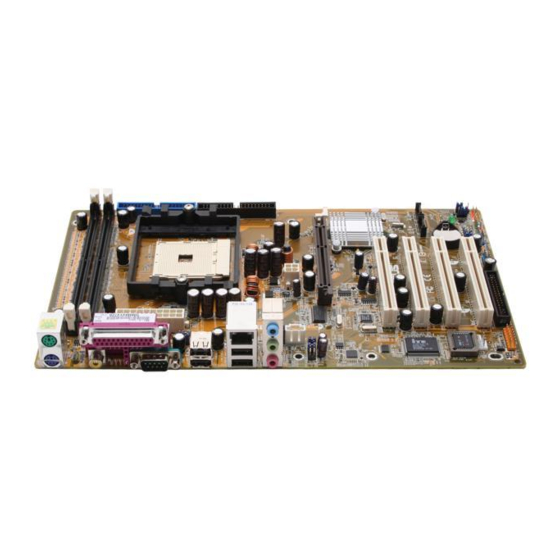
Chapter 1 1-3 Back Panel S1689 RJ-45 port PS/2 Printer Port Mouse Line-In port Line-Out port Microphone port PS/2 USB 2.0 ports Serial ports Keyboard 1-4 Motherboard Layout... -
Page 8: Chapter 2 Hardware Setup
Chapter 2 Chapter 2 Hardware Setup 2-1 PC D.I.Y. Assembly Instructions 1. Jumper Setting: Set the CPU External Clock, Frequency Ratio and the CPU voltage according to the instruction printed on the manual or silkscreen printed on the mainboard. 2. Installing FDD and IDE devices: Aligned the red colored edge of the cable with the pin 1 of the drive connector on the mainboard and gently attached it. - Page 9 Simply plug the cable into the respective device port or connector as shown in the manual or silkscreen printed on the mainboard. 8. Connecting the Power Supply Cables: Plug in the ATX power cable to the mainboard’s power connector and make sure the cable is connected.
-
Page 10: 自行組裝電腦之作業指導重點 (Chinese)
Chapter 2 2-2 自行組裝電腦之作業指導重點 (Chinese) 1. 主機板硬體組態設定: 依據使用手冊上面的指令或印刷在主機板上的文字來設定 CPU 外頻,倍頻及電 壓或其它設定。 2. 安裝 FDD 和 IDE 裝置: 將排線較長一端的排線插入主機板 IDE 插槽並且紅色線對準插槽的第一針腳 (Pin 1),檢視排線接頭是否完全插入插槽,同時排線較短的一端也依序插入軟碟 機,硬碟機等儲存裝置。 3. 安裝 CPU: 將 CPU 的缺角對準 CPU 腳座的缺角並小心地將 CPU 插在腳座上,按下旁邊的 固定桿以固定 CPU。 4. 安裝系統記憶體: 先確定記憶體模組金手指的方向,慢慢插入記憶體插槽並小心地將記憶體模組往 下壓,直到插槽的固定卡榫卡住記憶體模組兩端的缺口。... - Page 11 Chapter 2 5. 主機板固定: 用銅柱及螺絲將主機板安裝在機殼底座並確定每個孔洞均已被鎖上,尤其注意主 機板底下不可有多餘的銅柱以避免造成短路。 6. 增加介面卡: 將介面卡(例 : 網路卡,音效卡等)插在適當的介面卡擴充插槽,並將卡上的鐵片 鎖緊在機殼上。 7. 連接 I/O 埠和其他設備的接頭: 適當地將排線插入各設備的插槽,記得必須將排線與插座的第一針腳互相對準, 請參照使用者手冊的主機板平面圖。 8. 連接電源供應器: 將電源接頭與主機板上之插座對準插入,並確定卡榫已緊扣。...
-
Page 12: Français Instructions De Montage Du Pc D.i.y (French)
Chapter 2 2-3 Français Instructions de montage du PC D.I.Y (French) 1. Positionnement des cavaliers (jumpers) Positionnez les cavaliers de la fréquence d’horloge externe du microprocesseur, du rapport de fréquence et de la tension d’alimentation du microprocesseur, suivant les instructions qui figurent dans le manuel ou qui sont sérigraphiées sur la carte mère. 2. - Page 13 8. Raccordement des câbles de l’alimentation électrique Raccordez le câble d’alimentation ATX au connecteur d’alimentation de la carte mère, et vérifiez qu’ils sont bien verrouillés en place.
-
Page 14: Deutsch Pc D.i.y.-Montageanleitung (German)
Chapter 2 2-4 Deutsch PC D.I.Y.-Montageanleitung (German) 1. Steckbrücken Konfigureren Die Anweisungen zum Einstellen des externen Prozessortakts, der Taktfrequenz und der Prozesorspannung finden Sie im Hand buch oder direct auf dem Motherboard. 2. Disketten- und Festplattenlaufwerke Installieren Schließen Sie die rot markierte Kabelseite an Stift 1 des Laufweksanschlußes auf dem Motherboard an. - Page 15 Führen Sie die Karte vorsichtig in einen geeingneten Steckplatz ein. 7. Vo- und Geräteanschluße verbinden Verbinden Sie das Kabel mit dem ensprechenden Geräteanschluß. Folgen Sie dabei den Anweisungen im Handbuch oder direkt auf dem Motherboard. 8. Netzkabel anschließen Verbinden Sie das ATX-Netzkabel korrekt mit dem Netzanschluß auf dem Motherboard.
-
Page 16: Самостоятельная Сборка Пк (Russian)
Chapter 2 2-5 Самостоятельная сборка ПК (Russian) 1. Установка перемычек Установите параметры Вашего таймера ЦПУ, значение частоты и напряжение ЦПУ согласно инструкциям, приведенным в руководстве, или надписям на системной плате. 2. Установка Накопителя на гибких дисках и IDE устройств Совместите кромку красного цвета кабеля и PIN1 разъема накопителя на системной... - Page 17 7. Подсоединение портов ввода/вывода и разъемов устройств Подсоедините кабель к соотве5тствующему порту или разъему согласно инструкциям, приведенным в руководстве или напечатанным на системной плате. 8. Подсоединение кабелей источника питания Подсоедините кабель питания ATX к разъему питания системной платы и убедитесь в надежности крепления...
-
Page 18: Pc D. I. Y. 조립 설명 (Korean)
Chapter 2 2-6 PC D. I. Y. 조립 설명 (Korean) 1.점퍼설정 매뉴얼이나 메인보드에 나와있는 설정방법을 참고하여 CPU 의 외부클럭, 주파수, 전압 등을 설정합니다. 2. 메인보드 장착 드라이버를 이용하여 케이스에 정확하게 메인보드를 장착합니다. 3. CPU 장착 CPU 의 모서리를 보면 표시가 되어있습니다. 이 부분이 1 번 핀입니다. 이 부분을... - Page 19 1 번핀에 정확하게 장착합니다. 커넥터가 확실하게 연결될 수 있도록 하십시오. 6. 외부 카드의 장착 비디오카드 및 다른 외부 장착용 카드를 장착합니다. 7. I/O 포트, 기타장치 연결 매뉴얼이나 메인보드에 나와있는 설정방법을 참고하여 I/O 장치와 기타장치를 연결합니다. 8. 파워 써플라이 케이블 연결 ATX 파워케이블을 메인보드에 연결합니다. 감사합니다.
-
Page 20: Connector And Jumper Settings
While in Suspend mode, the LED light on the front panel of your computer will flash. Suspend mode is entered by pressing the Green Override Power Button on your ATX case, or by enabling the Power Management and Suspend Mode options in BIOS's Power Management menu. - Page 21 SL-SW (Sleep Switch): Some ATX cases provide a Sleep switch, which is used to put the system in Suspend mode. While in Suspend mode, the power supply to the system is reduced to a trickle, the CPU clock is stopped, and the CPU core is in its minimum power state.
- Page 22 Chapter 2 HD-LED (IDE - Activity LED Connector): The IDE- activity LED lights up whenever the system reads/writes to the IDE devices. FDD1 (Floppy Connector): The motherboard provides a standard floppy disk drive connector that supports 360K, 720K, 1.2M, 1.44M and 2.88M floppy disk types. It is connected to a floppy disk drive of 34 pins.
- Page 23 Chapter 2 JP3/4 (Power On by USB 0/1/2/3, 4/5/6/7): JP3 -> USB 0/1/2/3, JP4 -> USB 4/5/6/7 An USB keyboard hot key or an USB mouse-click can activate this board. To Enable Disable use this function, select a hot key of your (default) choice at the USB Resume from S3 option under Wake Disable Enable...
-
Page 24: Chapter 3 Phoenix Award Bios Setup Utility
Chapter 3 Chapter 3 Phoenix Award BIOS Setup Utility Phoenix-Award BIOS ROM has a built-in setup program that allows users to modify the basic system configuration. This information is stored in CMOS RAM so that it can retain the setup information even when the power is turned off. Press [Delete] when you Power on or Reboot the computer system. -
Page 25: Advanced Bios Features
Chapter 3 this. IDE Primary/Secondary Master/Slave Each of these items shows the name of the IDE devices currently connected to the motherboard. Drive A Allows users to choose the type of the floppy disk drive currently used. Available options: None, 360K, 5.25 in., 1.2M, 5.25in., 720K, 3.5in., 1.44M, 3.5in., 2.88M, 3.5in.. - Page 26 Chapter 3 performance thus will largely increase. Quick Power On Self Test This feature allows you to reduce the time it takes to boot up the system. If enabled, the BIOS will shorten the booting process by skipping certain some tests and shorten others.
- Page 27 Chapter 3 Gate A20 Option This BIOS feature is used to determine the method by which Gate A20 is controlled. The Normal option forces the chipset to use the slow keyboard controller to do the switching. The Fast option, on the other hand, allows the chipset to use its own 0x92 port for faster switching.
- Page 28 Chapter 3 wait before it starts repeating the keystroke. Generally, using a short delay is useful for people who type quickly and don't like to wait long for a keystroke to be repeated. On the other hand, a long delay is useful for users who tend to press the keys longer while typing.
-
Page 29: Advanced Chipset Features
Chapter 3 Show POST CODE Enabling this feature can show POST error code on the screen before proceeding to system’s operating system. 3-4 Advanced Chipset Features DRAM Configuration Max Memclock (Mhz) This feature allows you to select the memory clock. When it set to “Auto”, the system will automatically detect the memory clock. - Page 30 Chapter 3 the deactivation of active rows. Reducing the tRAS period allows the active row to be deactivated earlier. However, if the tRAS period is too short, there may not be enough time to complete a burst transfer. This reduces performance and data may be lost or corrupted. For optimal performance, use the lowest value you can.
- Page 31 Chapter 3 AGP Secondary Lat Timer This BIOS feature controls how long the AGP bus can hold the PCI bus (via the PCI-to-PCI bridge) before another PCI device takes over. The longer the latency, the longer the AGP bus can retain control of the PCI bus before handing it over to another PCI device.
-
Page 32: Integrated Peripherals
Chapter 3 3-5 Integrated Peripherals On-Chip Primary IDE Master PIO This feature allows users to set the PIO (Programmable Input/Output) mode for the IDE Primary Master drive attached to the IDE1 connector. Auto is recommended. Slave PIO This feature allows users to set the PIO (Programmable Input/Output) mode for the IDE Primary Slave drive attached to the IDE1 connector. - Page 33 Chapter 3 On-Chip USB1.1 Controller This feature allows users to enable/disable the USB1.1 controller. USB Keyboard Support This feature allows users to determine whether the USB keyboard is supported by the BIOS or the operating system. If users’operating system supports the USB keyboard, such as Windows XP, they shall disable this feature.
- Page 34 Chapter 3 Onboard FDC Controller This feature allows users to enable or disable the floppy disk controller. Onboard Serial Port 1 This feature allows users to select the I/O address and IRQ for the first serial port. Auto is recommended. Nevertheless, you can manually choose another I/O port or IRQ if a certain I/O port or IRQ is needed.
- Page 35 Chapter 3 use Full-Duplex if possible. Consult your IR peripheral's manual to determine if it supports Full-Duplex transmission. The IR peripheral must support Full-Duplex for this option to work. Use IR Pins Consult your IR peripheral documentation to select the correct setting of the TxD and RxD signals.
-
Page 36: Power Management Setup
Chapter 3 3-6 Power Management Setup ACPI Suspend Type This feature allows users to select the ACPI suspend type. You can select S1(POS) for Power On Suspend under ACPI mode, or S3 (STR) for Suspending To RAM. ACPI C2 Function This feature allows users to enable/disable ACPI C2 function. -
Page 37: Pnp/Pci Configurations
Chapter 3 prots off DPMS support: To select video power management values with Display Power Management Signaling support HDD Power Down Allows automatic power down of IDE drives after a specified period of inactivity, but 15 minutes is a suggested minimum, to avoid undue wear and tear on the drive. Suspend Mode This feature allows you to select the period of inactivity before the system is suspended or put into suspend mode. -
Page 38: Pc Health Status
Chapter 3 setting of Disabled after configuring the new ESCD. Therefore, the users need not to disable this feature after rebooting. Resources Controlled By This feature determines whether the BIOS will automatically configure IRQ and DMA resources or not. Auto is recommended. PCI/VGA Palette Snoop The VGA "palette"... -
Page 39: Load Optimized Defaults
Chapter 3 frequency for more than a moment. The BIOS usually offers two levels of modulation - 0.25% or 0.5%. The greater the modulation, the greater the reduction of EMI is. Therefore, if you need to significantly reduce your motherboard's EMI, a modulation of 0.5% is recommended. In most conditions, frequency modulation via this feature should not cause any problems. -
Page 40: Save And Exit Setup
Chapter 3 a password is required to enter both BIOS and the computer’s operating system (for example Windows XP) found on the boot drive. 3-12 Save and Exit Setup Save all configuration changes to CMOS (memory) and exit setup. A confirmation message will be displayed before proceeding. -
Page 41: Chapter 4 Software
Chapter 4 Chapter 4 Software Insert the support CD that comes with your motherboard into your CD-ROM driver or double-click the CD drive icon in [My computer] to enter the setup screen. 4-1 Driver Setup We begin with the installation of drivers. To do so, simply follow the instructions below. - Page 42 Chapter 4 Integrated Driver Five drivers are integrated into the item. They are ULi PCI 10-100 Fast Ethernet Controller Driver, ULi USB 2.0 Controller Driver, ULi PCI to AGP Controller Driver, ULi M5289 SATA Controller Driver, ULi M5289 SATA Raid Function. To install them, simply follow the instructions below Step-by-step guide 1.
- Page 43 Chapter 4 4. Ignore the message below and click Continue Anyway. 5. The following message simply tells you that it is better to install the driver prior to the potential installation of the graphics driver. 6. Choose Yes, I want to restart my computer now and click OK to restart the computer.
- Page 44 Chapter 4 DirectX 9.0c Allows you to install the latest DirectX 9.0c Driver. To do so, please follow the instructions below. Step-by-step guide 1. Click DirectX 9.0c to enter the Installing Microsoft DirectX. After reading the license agreement, choose I accept the agreement then click Next>. 2.
- Page 45 Chapter 4 3. Click Finish to complete the installation. Realtek Codec Audio Driver To install this, simply follow the instructions below. Step-by-step guide 1. Click Realtek Codec Audio Driver and wait until the figure below pops up. 2. Select Yes, I want to restart my computer now then click Finish to complete the process.
-
Page 46: Appendix
Appendix Appendix How to Install Windows 2000/XP On a SATA Drive After you unpack driver, please copy files under subdirectory SATA50XX to the root directory of floppy diskette (called driver diskette). Therefore, in root directory of floppy diskette you will see: (1) Files "disk1"... - Page 47 Note NOTE All rights are reserved for the products and corporate names/logos that appear in this manual to their original owners. We reserve all rights to change this manual .All information is subject to change without notice.
- Page 48 How to Contact CHAINTECH How To Contact CHAINTECH Please do not hesitate to contact us if you have any problem about our products. Any opinion will be appreciated. <Headquarters> For France, Europe: For Asia, Africa, Australia and Pacific AELT COMPUTER Island: 5 rue de Rome 93561 Rosny Sous Bois CHAINTECH COMPUTER CO., LTD...
Need help?
Do you have a question about the ULi M1689 and is the answer not in the manual?
Questions and answers