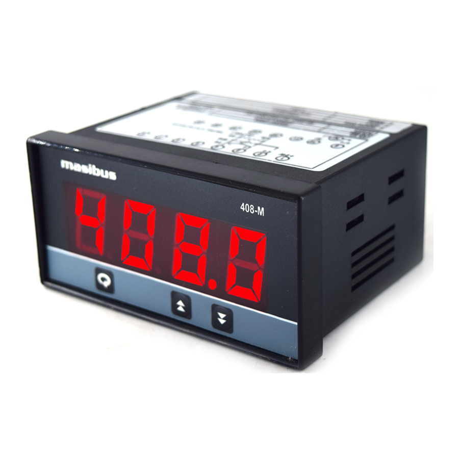
Masibus 408-M - Digital Indicator Quick User Manual
- User manual (36 pages) ,
- Quick user manual (2 pages)
Advertisement
MOUNTING DETAILS

ORDERING CODE
| Model | Input | Auxiliary Power Supply | ||
| 408-M | 1 | J | U1 | 85-265 VAC / 100-300 VDC |
| | 2 | K | ||
| 3 | T | U2 | 18-36 VDC | |
| 4 | R | | ||
| 5 | S | |||
| 6 | Pt-100 | |||
| C | 4-20mA | |||
| D | 0-20mA | |||
| E | 1-5 V | |||
| F | 0-5 V | |||
| G | 0-10 V | |||
TERMINAL CONNECTIONS

| Terminal No. | Description |
| 1 LPS+ | 24VDC Loop power supply Terminal 4 is ground Reference. |
| 2 C+ | For RTD Input Only (Three wire Compensation). |
| 3 TC+/ V+ | For Thermocouple, RTD &Linear Input |
| 4 TC- / V- / LPS- | |
| 9 L/+ | Power Supply Input |
| 10 N/- |
SAFETY/WARNING PRECAUSTIONS
To ensure that the device can be operated safely and all functions can be used, please read these instructions carefully.
Installation and Start-up must be carried out by qualified personnel only. The relevant countyspecific regulations must also be observed. Before start-up it is particularly important to ensure:
- Terminal wiring: check that all cables are correctly connected according to the connection diagram
- All wiring must confirm to appropriate standards of good practice and local codes and regulations. Wiring must be suitable for voltage, current and temperature rating of the system.
- Unused control terminals should not be used as jumper points as they may be internally connected, which may cause damage to the unit.
FRONT PANEL DESCRIPTION
| Name of Part | Symbol | Function |
| Increment Key |  |
|
| Decrement Key |  |
|
| Enter Key (Menu Key) |  |
|
| PV(Process Value)Display | PV |
|
PARAMETER SETTINGS
| Parameter (PV display) | Setting Name & Description | Default Value | |
| Symbol | Name | ||
| INPT (  ) ) | INPUT Type | Set PV Input Type (ReferTable1.1) | RTD.1 |
| ZERO (  ) ) | Zero | Automatically change to the Input Lower Range with changing of Input Type (ReferTable1.1) Can be set to any value within the Input Range & less the SPAN Value. | -199.9 |
| SPAN (  ) ) | Span | Automatically change to the Input Higher Range with changing of Input Type (ReferTable1.1) Can be set to any value within the Input Range & greater the ZERO Value. | 850 |
| *DP (  ) ) | Decimal Point | Set position of Decimal Point on Display. 0/ 0.0/ 0.00/ 0.000 0:0 1:0.0 2:0.00 3:0.000 | 0 |
| BRHT (  ) ) | Brightness | Adjust Brightness of the 7-segment Display. 10 to 100 | 50 |
| PASS (  ) ) | Password | Set Device Password 0 to 99 | 1 |
| VERS (  ) ) | Version | Shows the Version of the Current Firmware | - |
*parameter shows only if input type is linear.
 Mode
Mode
| (PV display) | Setting Name & Description | |
| Symbol | Name | |
| **AMB (  ) ) | Ambient | Ambient Adjustment |
| ZERO (  ) ) | Calibration Zero | Calibration Zero for PV Input(PV/SV Display: PV) |
| SPAN (  ) ) | Calibration Span | Calibration Span for PV Input(PV/SV Display: PV) |
**parameter showsonly if input type is TC.
MENU LAYOUT FOR 408-M

Examples:
How to change Set Point

How to change Input Type

SPECIFICATIONS
| Input type | Range |
| PT100 (0.1ºC) | -199.9 to 850.0 ºC |
| PT100 (1ºC) | -200 to 850ºC |
| J | -199.9 to 1200ºC |
| K | -199.9 to 1372ºC |
| T | -199.9 to 400ºC |
| R | 0 to 1768ºC |
| S | 0 to 1768ºC |
| *4-20mA /1- 5VDC | -1999 to 9999 (Field Scalable) |
| *0-20mA /0- 5VDC | |
| 0-10VDC |
*Use external 250ohms, 0.1% for current Input
Table 1.1
Inputs
| Input Type | Thermocouple, RTD (Pt100), Current, Voltage |
| Accuracy | |
| T /C and RTD: | +0.25% of FS + 1 degree |
| Linear: | +0.1% of FS + 1 count |
| Resolution | ADC:16bits Display: 0.1°C/1°C |
| Sampling Rate | 5 Samples/Sec |
| CJC Error | ±2.0°C Max |
| Sensor Burnout current | 0.25uA |
| RTD excitation current | 0.166mA (Approx.) |
| Allowable wiring resistance for RTD | Maximum 15 ohms/wire (Conductorresistance between three wires should be equal) |
| NMRR | > 40 dB |
| CMRR | > 120 dB |
| Input Impedance | > 1MΩ (Voltage Input) 250Ω (Current Input) |
| Max Voltage | 20VDC |
Display & Keys
| PV | 4-Digit 7-Segment, 0.8" High, Red |
| Keys | Enter, Increase, Decrease |
Output Types
| Loop Power Supply | 24VDC (±10%) @26mAwith Inbuilt Short Circuit Protection |
Power Supply
| Standard | 85-265VAC/ 100-300VDC |
| Optional | 18-36VDC |
| Power consumption | <5VA |
Isolation (Withstanding voltage)
- Between primary terminals* and secondary terminals**:
At least 1500 V AC for 1 minute - Between primary terminals* and grounding terminal:
At least 1500 V AC for 1 minute - Between grounding terminal and secondary terminals**:
At least 1500 V AC for 1 minute - Between secondary terminals**:
At least 500 V AC for 1 minute
* Primary terminals indicate power terminals and relay output terminals.
** Secondary terminals indicate analog I/O signal and Communication O/P.
Insulation resistance: 20MΩ or more at 500 V DC between power terminals and grounding terminal.
Physical
| Dimension (WxHx D )mm | 96 x 48 x 85 |
| Front Bezel(H x W) mm | 48 x 96 |
| Panel Cutout mm | 92 x 46 |
| Depth Behind Panel mm | 75 |
| Weight Approx. | 260g. |
| Enclosure Material | ABS Plastic |
| Enclosure Protection | IP 20 |
| Terminal Cable Size | 2.5mm2 |
Environmental Conditions
| TEMPCO | < 100ppm/°C |
| Humidity | 20% to 95% RH (Non-Condensing) |
| Ambient temperature | 0 to 55°C |
| Storage Temperature | 0 to 80°C |
Advance Feature
- Input scalability for linear input
For operation manual please visit www.masibus.com
Specifications are subject to change without notice due to Continuous improvements.
Masibus Automation And Instrumentation Pvt. Ltd.
B-30, GIDC Electronics Estate, Sector-25, Gandhinagar- 382044, Gujarat, India.
Tel: +91 79 23287275-79
Fax: +91 79 23287281
Web: www.masibus.comEmail: support@masibus.com

Documents / ResourcesDownload manual
Here you can download full pdf version of manual, it may contain additional safety instructions, warranty information, FCC rules, etc.
Download Masibus 408-M - Digital Indicator Quick User Manual
Advertisement


Need help?
Do you have a question about the 408-M and is the answer not in the manual?
Questions and answers