Table of Contents
Advertisement
Advertisement
Table of Contents

Related Manuals for Masibus 40005E


Summary of Contents for Masibus 40005E
- Page 1 USER MANUAL 40005E ENHANCED BARGRAPH INDICATOR Single Channel Dual Channel Masibus Automation & Instrumentation Pvt. Ltd. B/30, GIDC Electronics Estate, Sector-25, Gandhinagar-382044, Gujarat, India +91 79 23287275-79 +91 79 23287281-82 Email: support@masibus.com Web: www.masibus.com...
-
Page 2: Table Of Contents
Checking the Contents of the Package .................... 6 1.1 Product Ordering Code ......................7 2. INSTALLATION ..........................9 2.1 Safety Precautions in Installation ..................... 9 2.2 Mounting of 40005E ....................... 10 2.3 Maintenance and Inspection ....................11 3. HARDWARE SPECIFICATION ...................... 13 3.1 Input Specification ........................13 3.2 Output Specification ........................ -
Page 3: List Of Tables
40005E (Enhanced Bargraph Indicator) REF NO: m42B/om/101 Issue No:02 10.2 Exception Responses ......................55 10.3 Modbus Addresses ....................... 56 11. TROUBLESHOOTING ........................65 APPENDIX – A PV STATUS DURING SENSOR BURN OUT CONDITIONS ........66 APPENDIX – B HOW TO FETCH HISTORICAL DATA? ..............68 REVISION HISTORY : .......................... -
Page 4: List Of Figures
Figure 9 Back Plate Wiring Details ....................... 25 Figure 10 Communication Cable Connections ..................26 Figure 11 Functional Block Diagram of 40005E ................... 27 Figure 12 Program Mode Flow diagram ....................28 Figure 13 Configuration Mode Flow diagram ..................29 Figure 14 Configuration Mode Flow diagram .................. -
Page 5: Safety Precautions
40005E (Enhanced Bargraph Indicator) REF NO: m42B/om/101 Issue No:02 SAFETY PRECAUTIONS The product and the instruction manual describe important information to prevent possible harm to users and damage to the property and to use the product safely. Understand the following description (signs and symbols), read the text and observe Descriptions. -
Page 6: Introduction
Please read instructions carefully before altering any programming or configuration information. The 40005E module operates independently and can also be connected to a data Highway for remote systems communication functions through a personal computer or a distributed control system (DCS) using RS 485 or Ethernet communication. -
Page 7: Product Ordering Code
Issue No:02 1.1 Product Ordering Code The 40005E (Enhanced Bargraph Indicator) unit has a nameplate affixed to the one side of the enclosure. Check the model and suffix codes inscribed on the nameplate to confirm that the product received is that which was ordered. -
Page 8: Table 2 Product Ordering Code Description
40005E (Enhanced Bargraph Indicator) REF NO: m42B/om/101 Issue No: 02 Table 2 Product Ordering Code description 40005E Code Description Ch 1 PV Display Green Ch 1 Bar Display Green Not Applicable Ch 2 PV Display Green Not Applicable Ch 2 Bar Display... -
Page 9: Installation
To connect the protective conductor terminal to earth, complete these steps: 1) Use a spade lug to make contact with the metal surface of the 40005E. 2) Use a green and yellow wire to reliably earth the protective conductor terminal. Wire gauge must be no thinner than the current-carrying wire in the product‟s mains supply. -
Page 10: Mounting Of 40005E
40005E (Enhanced Bargraph Indicator) REF NO: m42B/om/101 Issue No: 02 2.2 Mounting of 40005E Mounting Method : Panel Mounting External Dimensions and Panel Cut Out Dimensions : Unit: mm Figure 1 Panel Cutout Dimensions User Manual... -
Page 11: Maintenance And Inspection
40005E (Enhanced Bargraph Indicator) REF NO: m42B/om/101 Issue No:02 Side View and Top View Figure 2 Side View and TOP view 2.3 Maintenance and Inspection This Section describes maintenance and inspection such as daily inspection, periodical inspection, and cleaning. - Page 12 40005E (Enhanced Bargraph Indicator) REF NO: m42B/om/101 Issue No: 02 through compliance tests. Installation state: Check for looseness of the cable connector and damage of the cable-No looseness or damage. Ambient environment: Check if the temperature and humidity are within the specified values.
-
Page 13: Hardware Specification
40005E (Enhanced Bargraph Indicator) REF NO: m42B/om/101 Issue No:02 3. HARDWARE SPECIFICATION 3.1 Input Specification NO. OF CHANNEL 1 or 2 APPLICABLE STANDARDS DIN (ITS-90) for Thermocouple and RTD INPUT TYPE As specified in Table 4. SAMPLING PERIOD PER 50 ms for TC and Linear Input and 100 ms for RTD... -
Page 14: Analog Output- Retransmission Output(Optional)
40005E (Enhanced Bargraph Indicator) REF NO: m42B/om/101 Issue No: 02 RELAY CONTACT RATING 250 VAC / 30 VDC @ 2A NO. OF RELAY OPERATION 1 X 10^5 @ rated current 3.2.2 Analog Output- Retransmission Output(Optional) NUMBER OF OUTPUTS 2 Max. -
Page 15: Display Specification
40005E (Enhanced Bargraph Indicator) REF NO: m42B/om/101 Issue No:02 3.7 Display Specification Ch- 1 : 4-digits, 7-segment, Red / Green , 0.3‟‟ character height CHANNEL DATA Ch- 2 : 4-digits, 7-segment, Red / Green , 0.3‟‟ character height DISPLAY BAR DISPLAY... -
Page 16: Environmental Specification
40005E (Enhanced Bargraph Indicator) REF NO: m42B/om/101 Issue No: 02 3.12 Environmental Specification AMBIENT TEMPERATURE -10 to 55°C HUMIDITY 30% to 95% RH (Non-Condensing) TEMPERATURE COEFFICIENT For All Analog input circuits < 100ppm WEIGHT 1.25 KG INSTRUMENT WARM-UP TIME <15 minutes after power on... -
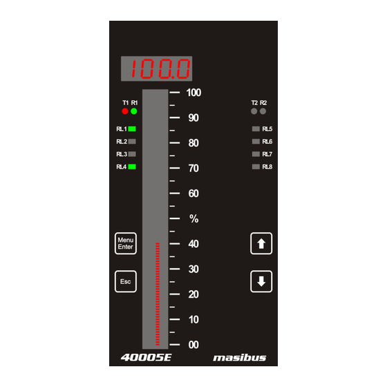
Page 17: Front And Rear Panel Diagram
40005E (Enhanced Bargraph Indicator) REF NO: m42B/om/101 Issue No:02 4. FRONT AND REAR PANEL DIAGRAM 4.1 Front Panel Diagram Figure 3 Front Panel Diagram for Dual Channel Name of Part Indication on Front Panel Channel Data Display Channel Data 101 LED segment for indicating Channel... -
Page 18: Key Function Description
40005E (Enhanced Bargraph Indicator) REF NO: m42B/om/101 Issue No: 02 4.2 Key Function Description Keys Operation It allows Mode Selection when pressed during Run mode, while it MENU/ENTER KEY allows saving value of a parameter inside a mode. When inside any mode, it allows to enter in sub-mode. -
Page 19: Connection Diagram
40005E (Enhanced Bargraph Indicator) REF NO: m42B/om/101 Issue No:02 5. CONNECTION DIAGRAM 5.1 Connection Terminal Details DO – RL Relay Terminals: 15 Pre-Feb. Cable Power Supply: Live (L/+), Neutral(N/-) and Earth ( Pre-Feb. Cable AI-1 Analog Input and Output: 12 ... - Page 20 Issue No: 02 Connect the protective conductor terminal to earth, Use a spade lug to make contact with the metal surface of the 40005E. All wiring must confirm to appropriate standards of good practice and local codes and regulations. Wiring must be suitable for Voltage, Current and temperature rating of the system.
-
Page 21: Cable Details
40005E (Enhanced Bargraph Indicator) REF NO: m42B/om/101 Issue No:02 5.2 Cable Details Digital Output – Relay Cable Details: Figure 7 Relay Cable Connection User Manual... -
Page 22: Table 6 Pin Details Of Relay Cable
40005E (Enhanced Bargraph Indicator) REF NO: m42B/om/101 Issue No: 02 Table 6 Pin Details of Relay Cable DIGITAL OUTPUT - RELAY ( DO - RL ) Sr. No. Connector Pin No. Pin Detail Ferrule No. COMMON - 1 NO -1 NC –... -
Page 23: Figure 8 Analog Input Output Cable Connection
40005E (Enhanced Bargraph Indicator) REF NO: m42B/om/101 Issue No:02 Analog Input Output Cable Details: Figure 8 Analog Input Output Cable Connection User Manual... -
Page 24: Table 7 Pin Details Of Analog Input Output Cable
40005E (Enhanced Bargraph Indicator) REF NO: m42B/om/101 Issue No: 02 Table 7 Pin Details of Analog Input Output Cable ANALOG INPUT OUTPUT ( AI-1 ) Connector Pin Sr. No. Pin Detail Ferrule No. AO 1 + AO 1 - AO 2 +... -
Page 25: Figure 9 Back Plate Wiring Details
40005E (Enhanced Bargraph Indicator) REF NO: m42B/om/101 Issue No:02 Back Plate Wiring Details: Figure 9 Back Plate Wiring Details User Manual... -
Page 26: Figure 10 Communication Cable Connections
40005E (Enhanced Bargraph Indicator) REF NO: m42B/om/101 Issue No: 02 Communication Cable Details: Figure 10 Communication Cable Connections RS485 Cabling Methodology should be Shielded single twisted pair cable. RS485 is designed to be used with a single twisted pair cable. It would reduce noise induced through ground potential differences. -
Page 27: Brief Operating Procedure
1) Connect Digital Output- Relay cable, Analog Input cable and Communication cable to 40005E as shown in figure 7,figure 8, figure 9 respectively. 2) Connect Power supply (Either 85-265 VAC or 18-36 VDC , as per the ordering code) to 40005E. The power on message on display will be “init”. -
Page 28: Menu Layout
40005E (Enhanced Bargraph Indicator) REF NO: m42B/om/101 Issue No: 02 7. MENU LAYOUT 7.1 Parameter Flow Diagram Figure 12 Program Mode Flow diagram User Manual... -
Page 29: Figure 13 Configuration Mode Flow Diagram
40005E (Enhanced Bargraph Indicator) REF NO: m42B/om/101 Issue No:02 Figure 13 Configuration Mode Flow diagram User Manual... -
Page 30: Figure 14 Configuration Mode Flow Diagram
40005E (Enhanced Bargraph Indicator) REF NO: m42B/om/101 Issue No: 02 Figure 14 Configuration Mode Flow diagram User Manual... -
Page 31: Figure 15 Calibration Mode And Security Mode Flow Diagram
40005E (Enhanced Bargraph Indicator) REF NO: m42B/om/101 Issue No:02 Figure 15 Calibration Mode and Security Mode Flow diagram Note : For All modes, Ch-2 and Ch-All will be displayed for Dual Channel Bargraph only. For Single Channel Bargraph, the value will be stored for Channel-1 by default. -
Page 32: Menu Parameters- In Detail
40005E (Enhanced Bargraph Indicator) REF NO: m42B/om/101 Issue No: 02 7.2 Menu Parameters- In Detail Note : For All modes, Ch-2 and Ch-All will be displayed for Dual Channel Bargraph only. For Single Channel Bargraph, the value will be stored for Channel-1 by default. -
Page 33: Table 8 Program Mode Parameters
40005E (Enhanced Bargraph Indicator) REF NO: m42B/om/101 Issue No:02 Table 8 Program Mode Parameters Program Mode Channel Shows Window Name Setting name and description Default value only if Symbol Password Password Asking for Password is other than zero Program Password... -
Page 34: Table 9 Configuration Mode Parameters
40005E (Enhanced Bargraph Indicator) REF NO: m42B/om/101 Issue No: 02 Table 9 Configuration Mode Parameters Configuration Mode Channel Shows Window Name Setting name and description Default value only if Symbol Password Password Asking for Password is other than zero Password... - Page 35 40005E (Enhanced Bargraph Indicator) REF NO: m42B/om/101 Issue No:02 applicable for (dP) Linear input type yes / no Sqrt Square root (Only 0(for all 2 (YES/NO) applicable for 0 : NO channels) (Sqrt) Linear input types) 1: YES ACJC/FCjC/CCJC (ACJC/FCJC/CCJC)
-
Page 36: Table 11 Input Type Selection
40005E (Enhanced Bargraph Indicator) REF NO: m42B/om/101 Issue No: 02 Table 11 Input Type Selection Type I/PNO Type Display Range Resolution none NONE E-Tc -200 to 1000C J-tc -200 to 1200C 0.1°C K-tc -200 to 1370C T-tc -200 to 400C B-tc 450 to 1800C... -
Page 37: Table 13 5 - Point Linearization
40005E (Enhanced Bargraph Indicator) REF NO: m42B/om/101 Issue No:02 LP08 LR08 8000 16.8 LP09 LR09 9000 18.4 LP10 100% LR10 9999 In above example Process Value on Display varies between: 1. 0 – 1000 for input of 0 % – 10% 2. -
Page 38: Table 14 Sub Parameters Of Do(Digital Output) Configuration Mode
40005E (Enhanced Bargraph Indicator) REF NO: m42B/om/101 Issue No: 02 Table 14 Sub Parameters of DO(Digital Output) Configuration Mode Sub parameters of DO(Digital Output) Configuration Mode Channel Setting name and Window Name Default value Shows only if description Symbol nr / fs do.lg... -
Page 39: Table 15 Do(Digital Output) Mapping Number And Its Description
Configuration DO(Digital Output) Configuration: Total numbers of relays in 40005E are 5. For one channel maximum Five numbers of DOs can be assigned. Among them one DO can only be assigned for control operation and four remaining DOs can be assigned for Alarm/Trip operatoin. Below example shows different configuration and different mapping of different DOs to 2 channels. - Page 40 40005E (Enhanced Bargraph Indicator) REF NO: m42B/om/101 Issue No: 02 Mapping and AS4. Mapping, Relay 3 is mapped to channel 1 in AS1. Mapping and AS2. Mapping. 6) Based On Watchdog Output ( Disable / Enable) selection , Error messages will be shown. i.e.
-
Page 41: Table 16 Do(Digital Output) Description
40005E (Enhanced Bargraph Indicator) REF NO: m42B/om/101 Issue No:02 8.4 Watchdog Timer(WDT) / Watchdog Output Operation. 7) Any DO can be mapped to W.D.MP(Watchdog Mapping) . Means, that particular DO is used as Watchdog Output. Note that, any DO which is assigned to A1.MP or A2.MP or A3.MP or A4.MP or C.S.MP cannot be mapped to W.D.MP and vice versa. -
Page 42: Table 18 Ao(Analog Output)(Retransmission Output) Description
40005E (Enhanced Bargraph Indicator) REF NO: m42B/om/101 Issue No: 02 1) None means no AO(Analog Output)(Retransmission Output) is assigned to particular channel. 2) AO O/p number = 0 represents “None” . AO O/p Number = 1 to 2 represents “Retransmission No. 1 to Retransmission No. 2”. For more details refer Table 18. -
Page 43: Table 20 Sub Parameters Of Display Configuration Mode
40005E (Enhanced Bargraph Indicator) REF NO: m42B/om/101 Issue No:02 Note 3: 1) CHANNEL Window shows sub parameter configuration name. i.e. while setting Ethernet IP (E.Ip.), Ethenet IP 1(E.ip.1) will be shown on same window. And so on. All sub parameters of Ethernet configuration will be shown as explained. - Page 44 40005E (Enhanced Bargraph Indicator) REF NO: m42B/om/101 Issue No: 02 1: YES p.l.HH Periodic Log 0 to 23 time - Hour (Refer Note 5) (P.L.HH) p.l.mm Periodic Log 0 to 59 time – Minute (Refer Note 5) (P.L.MM) p.l.ss Periodic Log 0 to 59 time –...
-
Page 45: Table 22 Calibration Mode Parameters
40005E (Enhanced Bargraph Indicator) REF NO: m42B/om/101 Issue No:02 4) Periodic Log time is settable in HH:MM:SS format. By default it is 00:00:01. 5) RTC related parameters are for setting date and time in Data logging. 3) Calibration Mode : By Pressing MENU key, CHANNEL window shows (CAL) message. -
Page 46: Table 23 Security Mode Parameters
40005E (Enhanced Bargraph Indicator) REF NO: m42B/om/101 Issue No: 02 DECREMENT key to modify value if required. OR press ESCAPE key and then INCREMENT Cf.md key to go to next parameter (CF.md). ESCAPE KEY is used to come out of CF.MD(sub parameter of Security mode). - Page 47 40005E (Enhanced Bargraph Indicator) REF NO: m42B/om/101 Issue No:02 Calibration and parameters will ALL-Set ALL values to set to default value F.RST = 2 factory default value (ALL) (Refer Note 6) Note 6: After resetting Calibration / Parameters / All values to factory reset values, the CHANNEL...
-
Page 48: Alarm Output, Control Output , Digital Output And Watchdog Output Operation
40005E (Enhanced Bargraph Indicator) REF NO: m42B/om/101 Issue No: 02 8. ALARM OUTPUT, CONTROL OUTPUT , DIGITAL OUTPUT AND WATCHDOG OUTPUT OPERATION 8.1 Alarm Output Operation Every single channel can have maximum 5 set points. 4 for Alarm outputs(1 for Alarm 1 Set Point , 1 for Alarm 2 Set Point, 1 for Alarm 3 Set Point, 1 for Alarm 4 Set Point) and 1 for Control Set Point, totaling 8 alarm outputs and 2 control outputs for 2 number of channels. -
Page 49: Table 26 Alarm 1 And Alarm 2 Maintained Alarm Logic
40005E (Enhanced Bargraph Indicator) REF NO: m42B/om/101 Issue No:02 Table 26 Alarm 1 and Alarm 2 Maintained Alarm Logic ALARM AL1 MAINTAINED ALARM (when in abnormal condition ack not pressed) NORMAL CONDITION NORMAL ABNORMAL UP (O/S) DOWN (O/S) HIGH ALARM... -
Page 50: Control Output Operation
40005E (Enhanced Bargraph Indicator) REF NO: m42B/om/101 Issue No: 02 8.2 Control Output Operation Control Output is the simplest form of temperature control. The output from the device is either on or off, with no middle state. For heating control, the output is on when the temperature is below the set point, and off above set point. -
Page 51: Watchdog Timer(Wdt) / Watchdog Output Operation
40005E (Enhanced Bargraph Indicator) REF NO: m42B/om/101 Issue No:02 8.4 Watchdog Timer(WDT) / Watchdog Output Operation The WDT, when enabled, operates from the internal Low-Power RC (LPRC) Oscillator clock source. The WDT can be used to detect system software malfunctions by resetting the device if the WDT is not cleared periodically in software. -
Page 52: Calibration Procedure
40005E (Enhanced Bargraph Indicator) REF NO: m42B/om/101 Issue No: 02 9. CALIBRATION PROCEDURE Calibration is provided for ambient temperature, PV sensor input, Analog Output (Retransmission output)(Optional). First select the calibration function as described below and then follow the procedure depending on the parameter to be calibrated. - Page 53 (rtr.1) . It indicates which Retransmission output needs to be calibrated. By pressing MENU key, CHANNEL window shows the value being outputted on Retransmission output terminals. In 40005E there are 2 number of Analog Output(Retransmission Output) are available. Now, measure the value using a highly accurate digital multi meter.
-
Page 54: Modbus Communication Detail
40005E (Enhanced Bargraph Indicator) REF NO: m42B/om/101 Issue No: 02 10. MODBUS COMMUNICATION DETAIL 10.1 Overview When ENHANCED BARGRAPH INDICATORs are setup to communicate on a Modbus network using RTU (Remote Terminal Unit) mode, each 8–bit byte in a message contains two 4–bit Hexadecimal characters. -
Page 55: Exception Responses
40005E (Enhanced Bargraph Indicator) REF NO: m42B/om/101 Issue No:02 Valid slave device addresses are in the range of 0 – 247 decimal. The individual slave devices are assigned addresses in the range of 1 – 247. Address 0 is used for the broadcast address, which all slave devices recognize. -
Page 56: Modbus Addresses
40005E (Enhanced Bargraph Indicator) REF NO: m42B/om/101 Issue No: 02 Exceptional Response: Table 33 Exceptional Response Byte Contents Example Slave Address Function 81 (80 + Function Code From Query) Exceptional Code CRC Hi CRC Lo Exception Codes Table 34 Exception codes... -
Page 57: Table 36 Details Of Abnormal Conditions Of Process Value
40005E (Enhanced Bargraph Indicator) REF NO: m42B/om/101 Issue No:02 Table 36 Details of abnormal Conditions of Process Value Abnormal Value (Integer) Description 32762 Reserved 32764 Channel Skip 32765 UNDER Value 32766 OVER Value 32767 Channel OPEN Indication Table 37 DO (Digital Output) Status Register and its bits arrangement... -
Page 58: Table 41 Holding Registers Parameters - Part 1
40005E (Enhanced Bargraph Indicator) REF NO: m42B/om/101 Issue No: 02 Table 41 Holding Registers Parameters – Part 1 Modbus Parameter Value Value Parameter Description Access Remarks Address Type (Single (Single Channel) Channel) Ch – 1 – AL1 – SET 40001 Integer Ch –... - Page 59 40005E (Enhanced Bargraph Indicator) REF NO: m42B/om/101 Issue No:02 Table 46 Refer ASP2 type for Channel 2 - 1 42036 - H (MSB- LSB) & Table 53 Table 46 Refer ASP3 Function for Channel 2 - 1 42573 - H (MSB- LSB) &...
-
Page 60: Table 43 Holding Registers Parameters - Part 3 And Calibration Registers Parameters
40005E (Enhanced Bargraph Indicator) REF NO: m42B/om/101 Issue No: 02 Table 43 Holding Registers Parameters – Part 3 and Calibration Registers Parameters Modbus Parameter Parameter Description Access Remarks Address Type Value Value Ambient calibration 42101 Integer -10.0 65.0 Ch –1 – CALZ... -
Page 61: Table 44 Input Type Selection Table
40005E (Enhanced Bargraph Indicator) REF NO: m42B/om/101 Issue No:02 – Channel 1 Linearization Range Step 9(LR09) 42599 Integer -1999 9999 – Channel 1 Linearization Range Step 42600 Integer -1999 9999 10(LR10) – Channel 1 Linearization Percent Step 42601 Integer 1(LP01) – Channel 2... -
Page 62: Table 45 Bit Accessible Holding Register Parameter - Square Root
40005E (Enhanced Bargraph Indicator) REF NO: m42B/om/101 Issue No: 02 K-tc 0 x 03 -200 1370 0.1°C T-tc 0 x 04 -200 0.1°C B-tc 0 x 05 1800 1°C R-tc 0 x 06 1750 1°C S-tc 0 x 07 1750 1°C... -
Page 63: Table 47 Parameter Applicability Selection
40005E (Enhanced Bargraph Indicator) REF NO: m42B/om/101 Issue No:02 Parameter ASP3 Function ASP3 Function Modbus 42573 42574 Address Parameter ASP3 Type ASP3 Type Modbus 42575 42576 Address Parameter ASP4 Function ASP4 Function Modbus 42577 42578 Address Parameter ASP4 Type ASP4 Type... -
Page 64: Table 59 Logging Enable Selection
40005E (Enhanced Bargraph Indicator) REF NO: m42B/om/101 Issue No: 02 Table 59 Table 60 Table 61 Table 62 Logging Enable Log Mode Factory Reset WatchDog Selection Selection Parameters Output Modbus Parameter Modbus Parameter Modbus Parameter Modbus Parameter Index value Index... -
Page 65: Troubleshooting
40005E (Enhanced Bargraph Indicator) REF NO: m42B/om/101 Issue No:02 11. TROUBLESHOOTING If the operating display does not appear after turning on the ENHANCED BARGRAPH INDICATOR ‟s power, follow the measures in the procedure below. If a problem appears complicated, contact our sales representative. -
Page 66: Appendix - A Pv Status During Sensor Burn Out Conditions
40005E (Enhanced Bargraph Indicator) REF NO: m42B/om/101 Issue No: 02 APPENDIX – A PV STATUS DURING SENSOR BURN OUT CONDITIONS PV INPUT STATUS DISPLAY DURING BURNOUT CONDITION: Table 63 PV Status during Burn Out Condition Display Input type Bar Display Message LED will be „OFF‟... -
Page 67: Table 64 Retransmission Output During Open/Over/Under Condition
40005E (Enhanced Bargraph Indicator) REF NO: m42B/om/101 Issue No:02 RETRAMISSION OUTPUT TABLE FOR OPEN /OVER /UNDER CONDITION (Optional): Table 64 Retransmission Output during Open/Over/Under Condition RETRASMI VARIABLE SCALE ACTION OPEN OVER UNDER ERROR SSION Holds the last Holds the last... -
Page 68: Appendix - B How To Fetch Historical Data
40005E (Enhanced Bargraph Indicator) REF NO: m42B/om/101 Issue No: 02 APPENDIX – B HOW TO FETCH HISTORICAL DATA? HOW TO FETCH HISTORICAL DATA : 1. For Periodic Logging: Periodic Data logging Record Frame Detail: Parameter Detail Bytes Log Frame detection (101,102) - Page 69 40005E (Enhanced Bargraph Indicator) REF NO: m42B/om/101 Issue No:02 Modbus Address for Periodic Data fetching: Modbus Parameter Parameter Description Access Remarks Address Type 42301- Data Fetched Periodic Log Integer 42375 Hold Data 42377 Integer Fetch Data 42376 Integer 42378- 42378 [Higher byte]...
- Page 70 40005E (Enhanced Bargraph Indicator) REF NO: m42B/om/101 Issue No: 02 Data for record number 5 - 6 will be loaded into data registers Write Fetch data = 1 Data for record number 7 - 8 will be loaded into data registers So in same manner data registers will be filled with 2 –...
-
Page 71: Revision History
Linearization note added in calibration procedure. Modbus parameters for Linearization added. 2. Version No. 02: Back Plate Wiring Details are added. Masibus Automation & Instrumentation Pvt. Ltd. Customer Support Division B/30, GIDC Electronics Estate, Sector-25, Gandhinagar-382044, Gujarat, India Ph: 91-079-23287275/23287276/23287277 Fax: 91-079-23287281 Email: support@masibus.com...
Need help?
Do you have a question about the 40005E and is the answer not in the manual?
Questions and answers