Table of Contents
Advertisement
Advertisement
Table of Contents

Related Manuals for Masibus 1006H


Summary of Contents for Masibus 1006H
- Page 1 User’s Manual FLOW INDICATOR TOTALISER 1006H Masibus Automation & Instrumentation Pvt. Ltd. B/30, GIDC Electronics Estate, Sector-25, Gandhinagar-382044, Gujarat, India +91 79 23287275-79 +91 79 23287281-82 Email: support@masibus.com Web: www.masibus.com...
-
Page 2: Table Of Contents
5.2 Mounting Steps ...................... 12 6. TERMINAL CONNECTION DETAILS ...............13 7. WIRING DIAGRAM....................14 7.1 Wiring Diagram of 1006H ..................14 7.2 Wiring Diagram and Jumper Setting of Pulse Input ..........15 7.2.1 NPN Proximity Input Jumper Setting ............... 15 7.2.2 PNP Proximity Input Jumper Setting ..............16 8. -
Page 3: Ref No:m16Aom101 Issue No
9.2.1 out zero and out span ..................29 10. COMMUNICATION GUIDELINES..............30 10.1 Introduction ......................30 10.2 Function Code for Modbus .................. 30 10.3 Modbus RTU protocol addresses for RS 485 Communication ......31 10.3.1 Addresses of 1006H ..................31 11. MISCELLANEOUS ....................33 12. Troubleshooting ......................34 User Manual... -
Page 4: Introduction
INTRODUCTION Forew ord Thank you for purchasing FLOW INDICATOR TOTALISER 1006H. This manual describes the basic functions and operation methods of 1006H. Please read through this user‟s manual carefully before using the product. Overview This is a microcontroller based Indicator - Totaliser unit, with very high performance to price ratio. - Page 5 Product Ordering Code: The FLOW INDICATOR TOTALISER 1006H unit has a nameplate affixed to the one side of the enclosure. Check the model and suffix codes inscribed on the nameplate to confirm that the product received is that which was ordered.
-
Page 6: Safety And Warning Precautions
Units suspected of being faulty must be disconnected and removed first and brought to a properly equipped workshop for testing and repair. Component replacement and interval adjustments must be done by a Masibus authorized or trained person only. -
Page 7: Specifications
Flow Indicator Totaliser 1006H REF NO:m16Aom101 Issue No: 03 3. SPECIFICATIONS 3.1 Measured input signal NUMBER OF INPUTS INPUT TYPE DC Input Current Input *Pulse Integrated/ 0-20 4-20 Input Batch Total 0-5 V 1-5 V MEASURING RANGE 0-30000 Range 0 - 999999 ACCURACY ±... -
Page 8: Contact Input (Digital Input)
Flow Indicator Totaliser 1006H REF NO: m16Aom101 Issue No: 03 3.4 Contact Input (Digital input) NUMBER OF INPUTS USAGE Input 1 : Start Batch /Stop Batch INPUT TYPE Non- voltage contact input or transistor open collector input 24VDC,10mA or more (for non – voltage contact input) -
Page 9: Isolation Specification
Flow Indicator Totaliser 1006H REF NO:m16Aom101 Issue No: 03 3.8 Isolation specification ISOLATION RESISTANCE Between power supply terminal and ground terminal: 500 VDC, 50MΩ MEASURED INPUT Isolated from other input/output terminals. Not isolated from TERMINAL 24Vdc supply (Transmitter power supply) and internal circuit. -
Page 10: Communication
Flow Indicator Totaliser 1006H REF NO: m16Aom101 Issue No: 03 3.12 Communication PROTOCOL Modbus RTU serial STANDARD EIA RS-485 MAX. COMMUNICATION DISTANCE 1200 mtrs. (For 9600 bps RS 485) COMMUNICATION METHOD 2 wire half duplex (RS 485) DATA FRAME N, 8, 1... -
Page 11: Front And Rear Panel Description
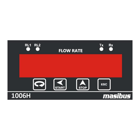
Flow Indicator Totaliser 1006H REF NO:m16Aom101 Issue No: 03 FRONT AND REAR PANEL DESCRIPTION 4.1 Front Panel Description 4.2 Rear Panel Diagram User Manual... -
Page 12: Mechanical Guidelines
Flow Indicator Totaliser 1006H REF NO: m16Aom101 Issue No: 03 MECHANICAL GUIDELINES 5.1 Mounting Details Mounting Method : Panel Mounting Panel cut-out: 92.00 mm X 44.00 mm 5.2 Mounting Steps Following steps should be followed for proper installation of the instrument. -
Page 13: Terminal Connection Details
Flow Indicator Totaliser 1006H REF NO:m16Aom101 Issue No: 03 TERMINAL CONNECTION DETAILS User Manual... -
Page 14: Wiring Diagram
Flow Indicator Totaliser 1006H REF NO: m16Aom101 Issue No: 03 WIRING DIAGRAM 7.1 Wiring Diagram of 1006H User Manual... -
Page 15: Wiring Diagram And Jumper Setting Of Pulse Input
Flow Indicator Totaliser 1006H REF NO:m16Aom101 Issue No: 03 7.2 Wiring Diagram and Jumper Setting of Pulse Input 7.2.1 NPN Proximity Input Jumper Setting 7.2.1.A NPN Proximity Input 7.2.1.B Dry Contact (With NPN Input Jumper Setting) User Manual... -
Page 16: Pnp Proximity Input Jumper Setting
Flow Indicator Totaliser 1006H REF NO: m16Aom101 Issue No: 03 7.2.2 PNP Proximity Input Jumper Setting 7.2.2.A PNP Proximity Input 7.2.2.B Dry Contact (With PNP Input Jumper Setting) User Manual... - Page 17 Flow Indicator Totaliser 1006H REF NO:m16Aom101 Issue No: 03 7.2.2.C Wet Contact >=10Vdc (With PNP Input Jumper Setting) 7.2.2.D Wet Contact <10Vdc (With PNP Input Jumper Setting) User Manual...
-
Page 18: Operating Details
Flow Indicator Totaliser 1006H REF NO: m16Aom101 Issue No: 03 OPERATING DETAILS The following paragraphs give detailed description of how to operate the unit. Before using the instrument, make sure to study and understand this section. 8.1 Display Section: The unit has Single window and it is groups of display: Six digits 7-segment, 0.56”... -
Page 19: Run Mode Parameters Details
Flow Indicator Totaliser 1006H REF NO:m16Aom101 Issue No: 03 8.3.1 Run Mode Parameters Details Name Description Max digits Limits Batch This parameter Max. 6 0 - 999999 Total displays the Total flow since batch is started („BT‟) Integrated Total This parameter Max. -
Page 20: Edit Mode
Flow Indicator Totaliser 1006H REF NO: m16Aom101 Issue No: 03 (only if BATCH TOTAL < (WP/EP) values. No new batch will be started by STOP key. When batch total value crosses the WP/EP value, relays gets OFF and batch is over. -
Page 21: Program Mode
Flow Indicator Totaliser 1006H REF NO:m16Aom101 Issue No: 03 8.4.1 Program mode Programming menu provides facility to configure the relay for different function. 8.4.1.1 Program Mode parameters Details Name Description No of Hi limit digit limit Low Alarm Alarm 999998... -
Page 22: Configuration Mode
Issue No: 03 8.4.2 Configuration mode Configuration mode provides facility to configure type of mode, type of input, baud rate for communication, etc. Every parameter is explained in the next section. 8.4.2.1 Configuration Mode Parameters of 1006H Name Description No Of... - Page 23 Flow Indicator Totaliser 1006H REF NO:m16Aom101 Issue No: 03 Note: - Retransmission Output is Corresponds to the ZR1 (Zero Value) and FS1 (Full Scale Value). Batch Mode: If „Batch Mode’ (bat md ) is selected to „Counter‟, then two parameters “Batch count”(bt Cnt) and “No of Batches”...
- Page 24 Flow Indicator Totaliser 1006H REF NO: m16Aom101 Issue No: 03 Note: To reset batch counter, Enter in batch count (bt Cnt ) parameter in configuration mode. Press “Start” key to see its value. Now if user presses “Stop” key Batch counter value will be cleared to 0.
- Page 25 Flow Indicator Totaliser 1006H REF NO:m16Aom101 Issue No: 03 Default Display: This parameter will select the parameter to be displayed in run mode. If Int tot / Bat tot is selected then in run mode „Integration total „/ „Batch total „will be displayed on lower panel accordingly.
-
Page 26: Calibration Mode
Flow Indicator Totaliser 1006H REF NO: m16Aom101 Issue No: 03 Pulse Time Pulse time is the average parameter for averaging of pulse input. Frequency Frequency can be selected as high and low. For pulse input frequency higher than 300Hz selects HIGH. For frequency less than 300Hz select LOW. -
Page 27: Parameter Flow
Flow Indicator Totaliser 1006H REF NO:m16Aom101 Issue No: 03 8.5 Parameter Flow How to operate menu is shown below in the form of flow diagram: User Manual... - Page 28 Flow Indicator Totaliser 1006H REF NO: m16Aom101 Issue No: 03 User Manual...
-
Page 29: Calibration Procedure
Flow Indicator Totaliser 1006H REF NO:m16Aom101 Issue No: 03 CALIBRATION PROCEDURE 9.1 Input Calibration As explained earlier, One can do calibration thro' the keyboard itself, Zero and Full-scale values are stored in NVRAM. 1. Switch on the instrument and allow 15 minutes of warm up time before starting calibration. -
Page 30: Communication Guidelines
Flow Indicator Totaliser 1006H REF NO: m16Aom101 Issue No: 03 COMMUNICATION GUIDELINES 10.1 Introduction The unit can be connected in RS-485 communication data link either in multi drop or repeat mode. Each unit must have unique Serial Number. Entire range of addresses (1 to 247) may be used. -
Page 31: Modbus Rtu Protocol Addresses For Rs 485 Communication
Flow Indicator Totaliser 1006H REF NO:m16Aom101 Issue No: 03 10.3 Modbus RTU protocol addresses for RS 485 Communication 10.3.1 Addresses of 1006H Sr. No. Reg. No. Parameter Name Length in Read/Write bytes (Words) 40001 High alarm 2(1) 40002 High alarm+2... - Page 32 Flow Indicator Totaliser 1006H REF NO: m16Aom101 Issue No: 03 Sr. No. Reg. No. Parameter Length in Read/Write byte (Word) 40036 2(1) 40037 SF4+2 2(1) 40038 2(1) R/W (0-9)* 40039 2(1) 40040 SF5+2 2(1) 40041 2(1) R (9) 40042 Baud rate...
-
Page 33: Miscellaneous
Flow Indicator Totaliser 1006H REF NO:m16Aom101 Issue No: 03 MISCELLANEOUS RETRAMISSION OUTPUT TABLE FOR OPEN /OVER /UNDER CONDITION: For 4-20mA:- DISPLAY RX O/P (mA) INPUT FEED (mA) SQUARE SQUARE LINEAR ROOT LINEAR ROOT I/P <1.60 OPEN OPEN 4.00 4.00 1.60<I/P<3.20... -
Page 34: Troubleshooting
If the operating display does not appear after turning on the controller‟s power, follow the measures in the procedure below. If a problem appears complicated, contact our sales representative. Masibus Automation & Instrumentation Pvt. Ltd. Customer Support Division B/30, GIDC Electronics Estate,...
Need help?
Do you have a question about the 1006H and is the answer not in the manual?
Questions and answers